
We can move through the
system design process
step by step:
The first requirement is imposed by the FEL system design, which is based on a cavity resonator with low (order 1%) extraction efficiency and modest instantaneous power output. The system achieves high average output power through the use of a very high repetition rate, thereby avoiding many of the difficulties inherent in low-rep-rate, high peak power systems, such as transport of a space charge dominated beam. The FEL is optimized to use a 42 MeV electron beam with 5 mA current delivered in ~135 pC bunches at a 37.5 MHz repetition rate. In order to achieve laser operation, peak current requirements demand bunch lengths on the order of 1 psec at the wiggler, from a beam of ~0.5% momentum spread and normalized rms emittance of <~ 13 mm-mrad. Electron beam/optical mode overlap requirements in the FEL demand betatron matching into the wiggler; the peak current needed for the design FEL gain requires use of bunch length compression for longitudinal phase space management.
The second requirement embodies the implementation of energy recovery to limit RF power requirements, reduce costs and manage radiation. Inasmuch as the beam full momentum spread after the wiggler will be ~5%, this demands low loss transport of a large momentum spread beam.
The need for transverse matching and longitudinal phase space management before the wiggler implies the need for some type of quadrupole matching telescope(s) and a bunch compression system. The high current and low energy chosen to drive the IR FEL implies that collective effects will be important. To avoid space charge driven beam quality degradation, a moderately high injection energy (10 MeV) is selected. Beam break-up (BBU) and other impedance-driven instabilities must be avoided. Coherent synchrotron radiation (CSR) must be managed to avoid emittance degradation. RF stability must be assured, particularly in transient regimes such as FEL turn-on and during initiation of energy recovery.
Beam transport for energy recovery must limit beam losses while managing a large momentum spread beam (~5%, downstream of the wiggler). This implies that careful control of beam envelopes and lattice chromatic and geometric aberrations must be provided over large volumes of the transverse/longitudinal phase space. Variable momentum compaction is needed to allow for energy compression and optimization of RF stability during energy recovery. This limits the momentum spread and enhances the stability of the 10 MeV energy recovered beam during transport to the dump.

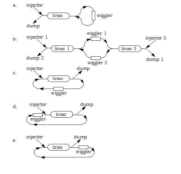
These configurations have the following topologies:
Topologies c, d, and e all avoid obvious RF hardware problems, but differ in the emphasis placed on various physical phenomena. Options c and d both limit the bending of the (large momentum spread) energy recovered beam, but introduce considerable bending of the FEL drive beam. This simplifies the process of energy recovery, but suggests that CSR and space charge driven emittance growth are potential problems. We have therefore selected option e; this choice minimizes the impact of CSR and space charge on the FEL drive beam, at the cost of increased complexity in the energy recovery transport. It also allows for "straight-ahead" operation of the machine as a simple linac (without energy recovery) to drive the FEL at low powers during initial (commissioning) operation. The design solution for this topology is discussed briefly below and in greater detail elsewhere (if you have jumped here from the "IR Driver Lattice Solution" page).
Certain requirements must be globally met. The transport system must confine beam spots and envelopes through acceleration, lasing, and energy recovery. Requirements should be met simply, with mechanically robust, low cost components (preferably already in the Jefferson Lab component inventory). As the system handles very low energy beam, dipoles will tend to bend through large angles and impose significant focusing. The effect of dipole edge angles, gaps, and field rolloff should therefore be incorporated in design computations.
Finally, the system should avoid aggravating collective effects such as CSR, BBU, space charge, or other instabilities. PARMELA studies indicate space charge is important only at low energy; in the parameter regime of interest it may be neglected at 40 MeV. We can therefore use standard single particle optics design tools. This is a pleasant consequence of the modest single bunch currents employed in this FEL concept - high FEL power is generated with a high repetition rate, not a high efficiency! Related details and a discussion of operational aspects of this issue are given on the IR FEL Driver Lattice Solution page.
| Project Overview | |
| System Design Process | |
| **you are here! ** | Application of Process to High Power IR FEL |
| **the next link is | Description of Solution |
| System Performance | |
| Error Studies | |
| Upgrade Scenarios | |
| | |
| Go to The FODOmat's FEL Page | |
Last modified: 25 March 1997
http://www.jlab.org/~douglas/
is maintained by: douglas@jlab.org