or
"Revenge of the Pion Prescaling Circuit"
Dave Gaskell
Jan. 27, 2005
I. Computer Dead Time Calculation the Easy Way (NOT the way we will do it)
The standard way to determine the computer dead time is straightforward. If there is only one trigger type, then we measure exactly the number of events we miss when the computer is busy. Let's review quickly a trigger signal's progression through the electronics (see Fig. 1).
Figure 1: Trigger supervisor logic. Note that the HMS (SOS, COIN) TRIG outputs are inhibited by the TS BUSY signal.
1) A pretrigger is formed. Whatever the trigger may be (3/4-SCIN, ELREAL, ELCLEAN), we get an output from the pretrigger module. This signal is sent to scalers and is also sent on the 8LM.
2) The 8LM does its thing and, if it is not inhibited, passes the pretrigger signal on, and creates a corresponding trigger signal, which is sent to the trigger supervisor.
Note that the 8LM can be inhibited by a signal from the trigger supervisor. If the trigger supervisor is busy, it lets the 8LM know to not send on any more trigger signals. So the trigger output may be inhibited, BUT the pretrigger out of the 8LM is never inhibited.
3) At the trigger supervisor, the trigger signal is processed and either prescaled away, or initiates the ADC and TDC readout of the event. While an event is being read out, the trigger supervisor outputs the TS BUSY signal, which is sent back to the 8LM.
4) The number of events lost due to the computer being busy is simply obtained from ratio of triggers (events coming out of the 8LM and not inhibited) to pretriggers (events going into the 8LM).
Computer live time = (HMS TRIG)/(HMS
PRE)
Piece of cake.
II. Computer Dead Time Calculation the Hard Way (the way we will do it)
II.A The problem:
The above, simple, calculation assumes that we have a single trigger type. In principle, multiple trigger types are not a problem so long as the rate of one trigger type is not enormously different from the other.
In our case, the pretrigger was given by the .OR. of the electron trigger (ELREAL) and the dynamically pre-scaled pion trigger (PIPRE). In principle, the pion prescaling circuit is set up to heavily prescale the SCIN trigger when the SCIN rate is high (allowing something like a maximum rate of 100 Hz) and to take basically all SCIN triggers at low SCIN rates.
A schematic of the pion prescaling circuit is shown below. John A.'s thesis has a nice description of how the pion-prescaling circuit works. The output of 2 cascaded gate generators is ANDed with the 3/4-SCIN signal and sent to the pretrigger module. The two gate generators are used to prescale the pions as follows:
The start to the first gate is enabled when the second gate's output is disabled, and vice versa. Assume the first gate is enabled - this will disable the second gate for 10 ms. After that time, the second gate is enabled for, at most, 20 ms. If a SCIN signal arrives in that time, it will send a stop signal to the second gate generator, thus enabling the first. So, at high SCIN rates, there will always be at least 10 ms between PIPRE signals, giving a maximum rate of ~ 1/10 ms = 100 Hz. At low pion rates, the second gate will stay open some large fraction of its 20 ms gate width, yielding a prescale of ~ 20/(10+20) = 2/3, so the circuit allows 2/3 of the 3/4-SCIN signals at low rates.
So far so good. So what's the problem? During x>1, EMC effect the problem became most noticeable during positron running. In that case, the main signal (the ELCLEAN trigger) was very low rate. On the other hand, the SCIN rate was very high because we had all kinds of protons and pions in the acceptance. In principle, the pion-prescaling circuit should have handled this and only allowed about 100 Hz of SCIN triggers through - a low enough rate that we should have seen almost no effect on the computer dead time. But, we saw seemingly huge computer dead times when looking at the ratio of triggers to pretriggers.
This was a puzzle - we were really losing triggers, the scalers don't lie. But the average rate was very low. The computer should have been able to handle it no problem.
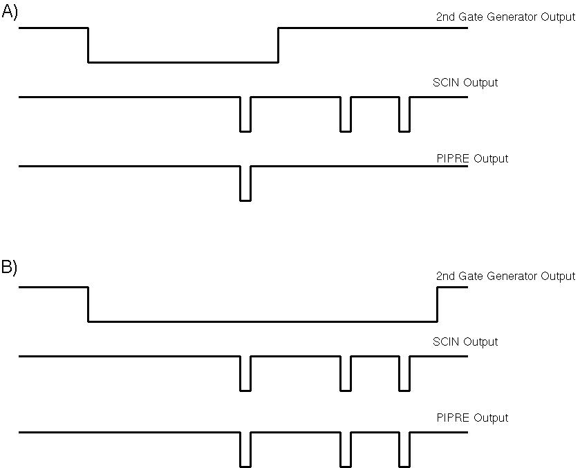
The cause, in the end, came from the pion prescaling circuit. Recall that, once a SCIN signal has arrived while the second gate generator is open, a signal is supposed to be fed back closing that gate, thus starting the 10 ms wait period of the first gate generator. However, it was apparent that the second gate was not always being stopped appropriately after a SCIN signal arrived. I looke at some signals on the o'scope and below I've drawn how things SHOULD look and how they REALLY looked.
The diagram labelled "A" denotes how things should work. The signal from the 2nd gate generator is open (1st trace) - a SCIN signal (2nd trace) arrives while the gate is enabled and a PIPRE is formed (3rd trace). The PIPRE disables the gate generator and subsequent SCIN signals do not form a PIPRE.
Diagram B shows what actually would happen (not all the time, but often). The SCIN signal arrives while the gate is open, a PIPRE is formed, but the PIPRE, for some reason does not close the gate. Two more SCIN signals follow and more PIPRE signals are formed. Keep in mind though, that computer is now busy (for something like a few hundred microseconds), and if the "extra" PIPRE signals are arriving within that time, they will be lost leading to an abnormally large computer dead time.
Note that these extra lost events are predominately PIPRE signals (they could block a few extra ELCLEANs, but not too often). So, now we are in the situation where the computer is probably accepting almost all the ELCLEAN (or ELREAL) signals, but losing a bunch of PIPRE signals, but our normal computer dead time calculation can't tell the difference. What do we do?
II.B The Solution
Fortunately, we send all our trigger signals not only to scalers, but to TDCs as well. This means we can actually determine event-by-event which leg of the trigger was fired, i.e., if the event was an electron (ELREAL or ELCLEAN) or prescaled pion (PIPRE). So now, rather than taking the simple TRIG/PRETRIG ratio, we need to calculate, for example,
Computer livetime (for ELREAL
triggers) = TRIG (with hits in ELREAL TDC)/PRETRIG(ELREAL)
To obtain the number of ELREAL TDC events, we can define a CTP test that looks at the actual TDC value and records the number of times a event occurs in the defined range. The ELREAL PRETRIG events we can infer from the simple ELREAL scaler. Note however that this signal is the number of ELREAL events going into the pretrigger module, not the number coming out. Since the pretrigger hardware gate width is a little wider, we will lose a few ELREAL events, so the ELREAL scaler number will be a slight over-estimate (by about 1/(1-10 ns * (ELREAL-rate)).
But don't forget about the prescale! The TDCs are only read out every time there is an actual trigger, but we sometimes prescale the triggers. So actually, the computer live time is,
Computer livetime (for ELREAL
triggers) = PS*TRIG (with hits in ELREAL TDC)/PRETRIG(ELREAL)
Since we need to always correct for the prescale anyway, it's convenient to just define a combined computer live time and prescale efficiency:
We have the above accessible in the ENGINE now. However, we need to refine our cuts on the TDC for the relevant triggers. Note that for consistency, we should use the same cuts on the actual data (since we have that information in our ntuples). Also, we should not forget to account for the slight difference between ELREAL and PRETRIGGER gate widths, although this effect should be really small.
Since we need to always correct for the prescale anyway, it's convenient to just define a combined computer live time and prescale efficiency:
Computer livetime (for ELREAL
triggers)/PS = TRIG (with hits in ELREAL TDC)/PRETRIG(ELREAL)
Dividing your yield by the above will
simulaneously correct for the prescale factor and computer live time
all at once.
We have the above accessible in the ENGINE now. However, we need to refine our cuts on the TDC for the relevant triggers. Note that for consistency, we should use the same cuts on the actual data (since we have that information in our ntuples). Also, we should not forget to account for the slight difference between ELREAL and PRETRIGGER gate widths, although this effect should be really small.