Hall C Target Configuration
For May 2007
David Meekins
Target Positions
The following table gives a list of target positions and materials. (Listed BDS positions are pre corrections for cryo and vacuum motion). The home position will remove the entire target stack from the beam.
Solid Target Ladder
The following table gives the target foil position, thicknesses and chemical purities.
|
Target Position |
Target |
Purity |
Thickness g/cm2 |
|
Empty |
n/a |
n/a |
n/a |
|
BeO |
Ta |
99.0% |
0.2918 ± 0.0003 |
|
Carbon |
Carbon |
99.95% |
0.35525 ± 0.00030 |
|
Copper |
Copper |
99.95% |
0.17775 ± 0.00015 |
|
Iron |
Iron |
99.5% |
0.1187 ± 0.00014 |
Error in thickness is
from measurement of area and mass only.
Outside thickness (measured with micrometers) variations in the foils
are less than the reported error. Error
also does not include possible voids in materials.
Fluid Targets
The following table and describes the cell orientation and wall thicknesses as seen from the top. The cell material is Al 7075-T6.
The table below gives the thicknesses of the cell wall at each of the 4 lettered positions. The OD is the outer diameter of the cell.
|
Cell |
|
A (mm) |
B(mm) |
C(mm) |
D(mm) |
OD (mm) |
|
1 |
1 |
0.1384±0.0013 |
0.1359±0.0013 |
0.1270±0.0013 |
0.1308±0.0013 |
40.13±0.0013 |
|
2 |
2 |
0.1219±0.0013 |
0.1181±0.0013 |
0.1219±0.0013 |
0.1207±0.0013 |
40.18±0.0013 |
|
3 |
3 |
0.1232±0.0013 |
0.1232±0.0013 |
0.1194±0.0013 |
0.1118±0.0013 |
40.16±0.0013 |
Optics Targets
The optics target has 3 positions. The first position has 3 foils on each at z = ± 7.5 cm and 0; the second has positions at z = ± 2 cm; the third has positions at z = ± 3.8 cm. The following table gives the foil thickness and positions. Carbon foils are 99.95% carbon. Positions less than 0 are upstream from the nominal target center.
|
Position |
Z position |
Material |
Thickness (g/cm2) |
|
3 foil |
Z = -7.5 cm |
Al 6061-T6 |
0.2651 ± 0.0020 |
|
3 foil |
Z=0 |
Al 6061-T6 |
0.2658 ± 0.0020 |
|
3 foil |
Z = 7.5 cm |
Al 6061-T6 |
0.2672 ± 0.0020 |
|
2 foil z = ± 2 |
z = + 2 |
Carbon |
0.1659 ± 0.0012 |
|
2 foil z = ± 2 |
z = +-2 |
Carbon |
0.1654 ± 0.0012 |
|
2 foil z = ± 3.8 |
z = +-3.8 |
Al 6061-T6 |
0.2663 ± 0.0020 |
|
2 foil z = ± 3.8 |
z = +-3.8 |
Al 6061-T6 |
0.2600 ± 0.0019 |
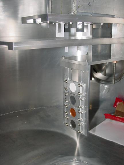
Each of these targets is 25 mm wide at the beam interaction point. Please see picture to get a better view of the configuration.
Dummy Targets
The dummy target consists of 2 aluminum alloy foils placed at z = ± 2 cm. The foils are 0.8 cm wide (beam transport x direction). The following table gives the positions and thicknesses of these foils. The alloy is Al6061-T6.
|
Foil Number |
Position |
Thickness (g/cm2) |
|
Foil 1 |
Upstream foil |
0.2658 ± 0.0035 |
|
Foil 2 |
Downstream foil |
0.2549 ± 0.0034 |
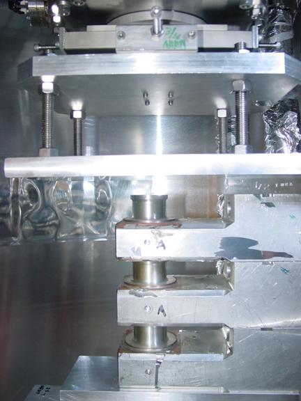
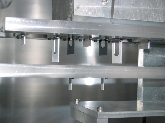
Pictures
Greg Smith was kind enough to provide the following pictures of the target stack.