 |
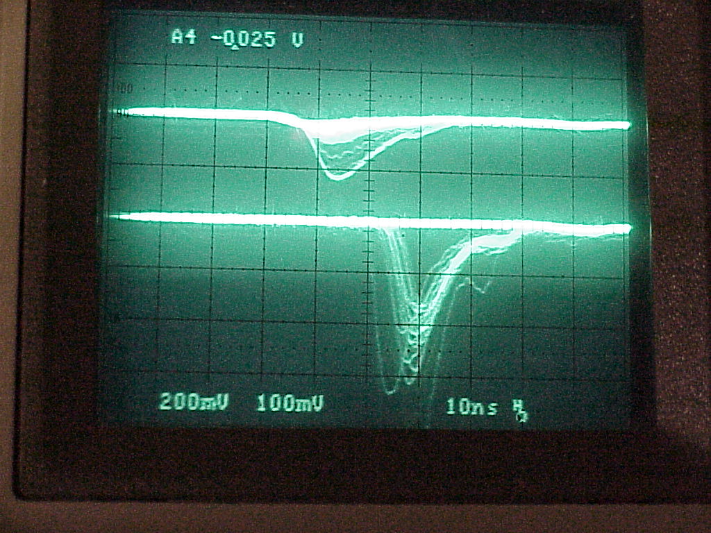
Step 1.
E (up) and DE (down) signal triggered from the
|
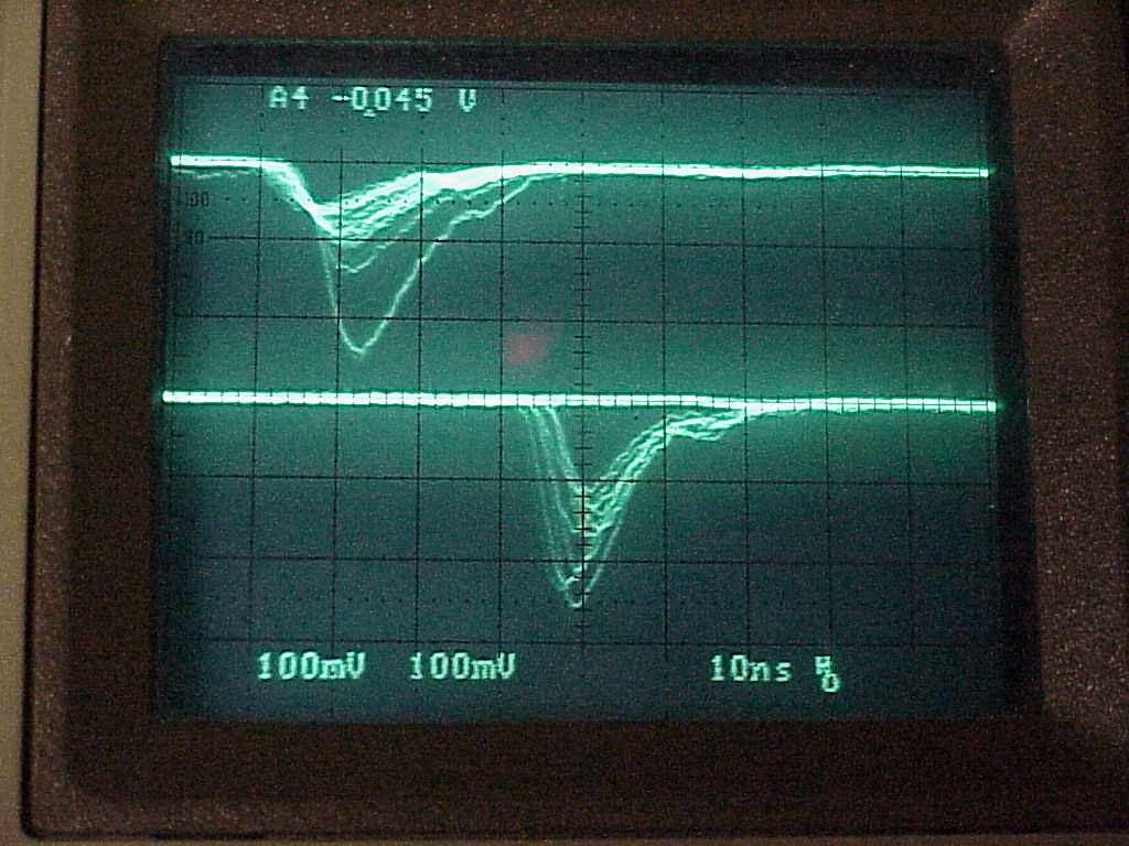 |
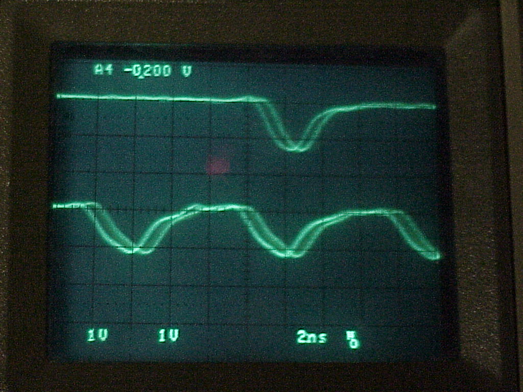
Step 2.
E (up) and DE (down) signal triggered from the
|
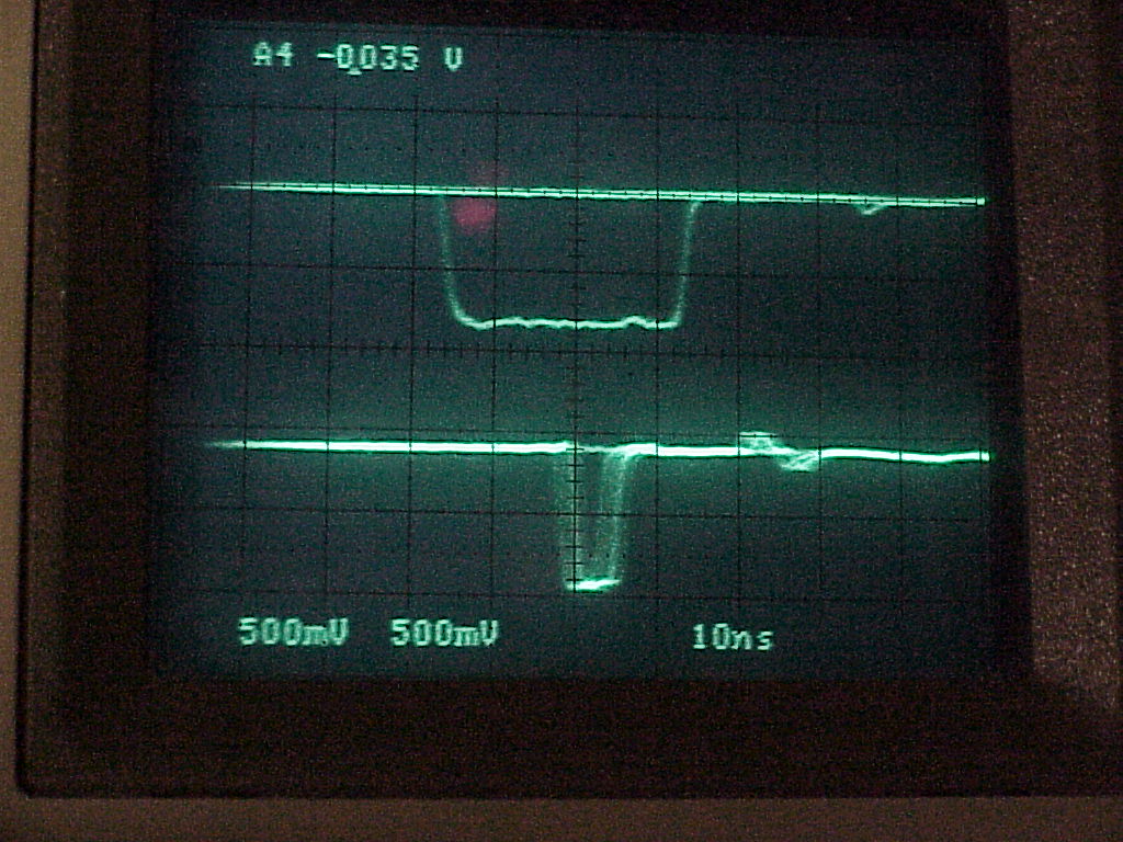 |
Step 3.
E trigger gate (30ns) and
DE trigger gate (5ns).
|
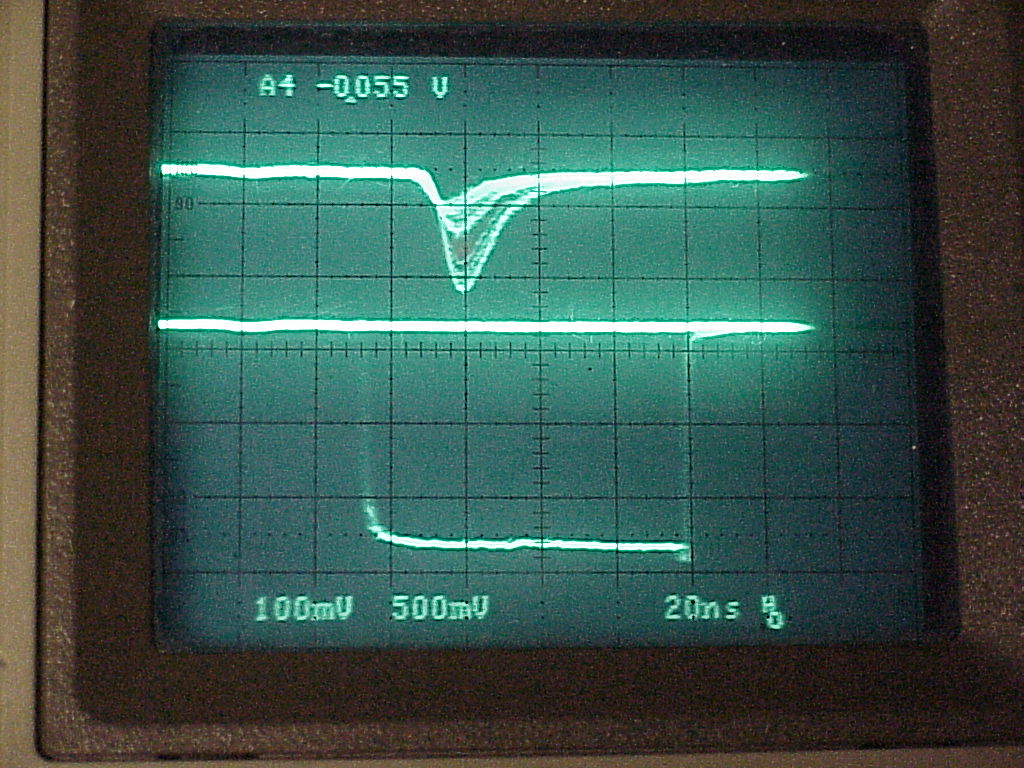 |
Step 4.
E signal and ADC gate triggered on E (~55mV),
|
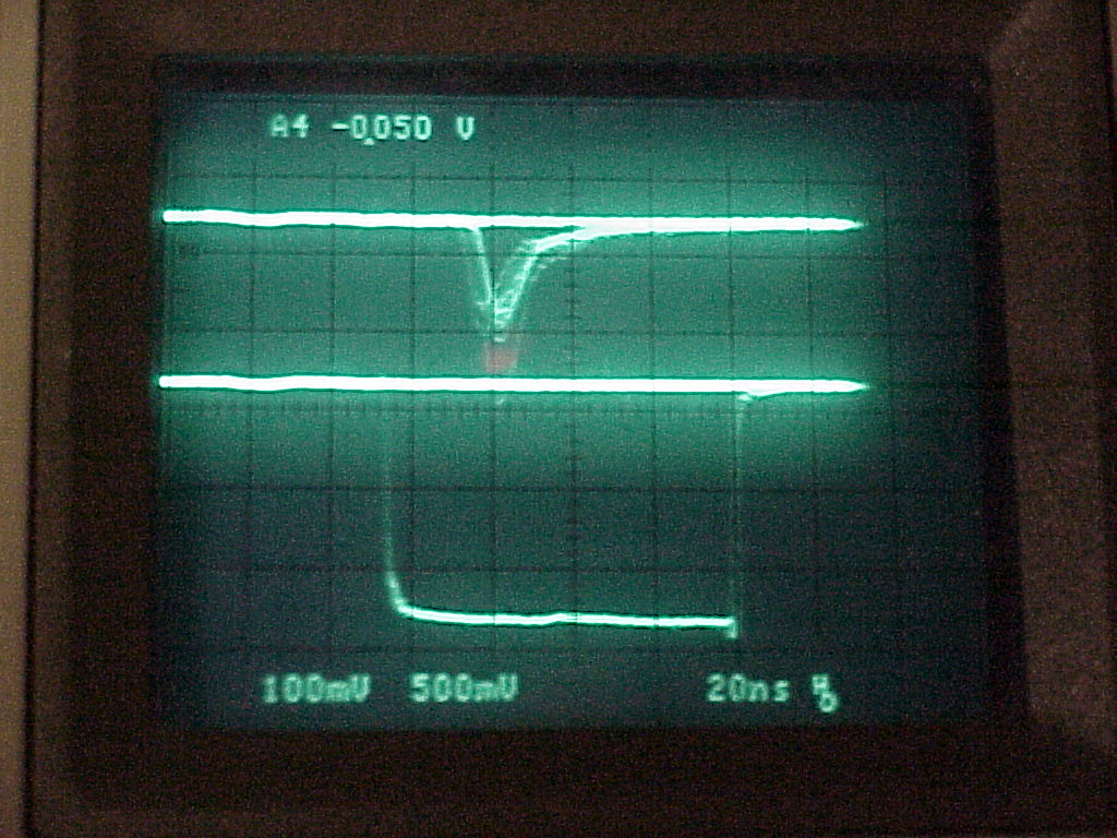 |
Step 5.
DE signal and ADC gate trigger E signal (~50mv),
|
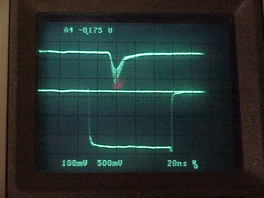 |
Step 6.
DE signal and ADC gate trigger E signal (-125mV) level.
|
 |
Step 7.
Coincidence of E, DE and 125Mhz signals.
|
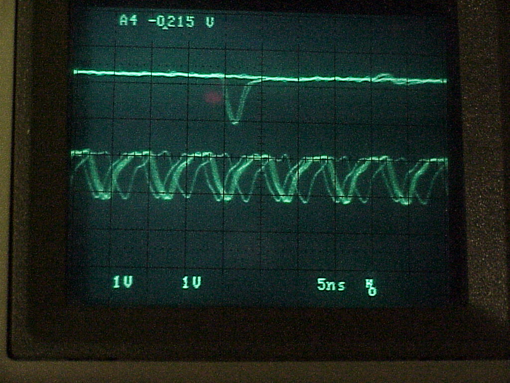 |
Step 8.
Coincidence of E, DE, and 125 Mhz.
|
 |
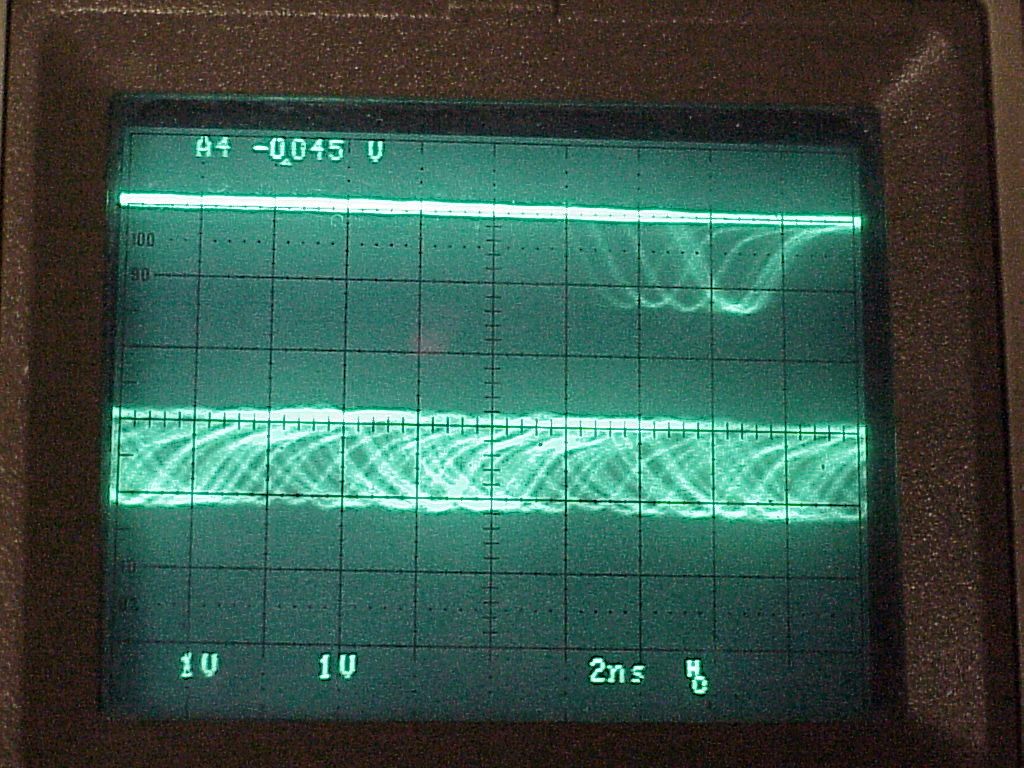
Step 9.
Like Step 8, but time scale is 2 ns.
|