|
|
-
For counting, timing, and energy spectroscopy with scintillation
detectors and proportional counters
-
Selectable shaping times (0.5, 1.5, and 3.0 s)
-
High count-rate capability
|
-
Gated active baseline restorer
-
Selectable window range
-
Integral/Window mode
|
| The ORTEC Model 590A Amplifier and Timing
Single-Channel Analyzer includes both a low-noise shaping amplifier and
a timing single-channel analyzer. |
| The amplifier employs active-filter shaping
(0.5, 1.5, and 3.0 µs shaping times) for use with various types of
radiation detectors. It is particularly well suited for use with the proportional
counters and scintillation detectors normally used in x-ray and nuclear
spectroscopy, as well as in x-ray diffraction and Mössbauer experiments.
High amplifier gain improves operation of proportional counters because
they can be used with lower operating potentials, thus improving the stability
of gas gain vs count rate. The amplifier's short resolving time provides
high count-rate capability without sacrificing the energy resolution of
the proportional counter. |
| The amplifier has a single output that can
be switch-selected for either unipolar or bipolar pulse shaping. The unipolar
output is used for spectroscopy in systems where dc-coupling can be maintained
from the Model 590A to the analyzer. A baseline restorer, (BLR) circuit
is included in the amplifier for improved performance at all count rates.
Baseline correction is applied only during intervals between input pulses,
and the discriminator level to identify input pulses is automatically adjusted.
The unipolar output dc-level is within the range from 5 mV to +5 mV. This
output permits the use of the direct-coupled input of the analyzer with
a minimum amount of interface problems. |
| The timing single-channel analyzer, (TSCA),
in the Model 590A is dc- coupled to maintain the peak in an adjusted window
without shifts due to changes of count rates. This permits stable operation
with narrow window widths over wide variations of count rates, such as
those that are usually present during x-ray diffraction studies. The lower
level can be adjusted with a front-panel control, or it can be set by an
external voltage. |
| The TSCA output occurs ~500 ns after the peak
of the amplifier output signal. The walk of this signal is very small over
a wide range of input amplitudes, making the Model 590A ideal for use in
slow coincidence or gating applications. |
| The External Lower Level, (Ext LLD), input
of the Model 590A can be used with an external voltage to set the lower
level. It can also be used with a slowly varying voltage to change the
lower level as a function of time or other measurement parameters. |
|
PERFORMANCE (Amplifier)
|
| Shaping Semi-Gaussian on all ranges with
peaking time equal to 2.2t and pulse width at
0.1% level equal to 4 times the peaking time. Bipolar crossover equal to
1.5t . |
| Gain Range Continuously adjustable from X5
through X1250. |
| Integral Nonlinearity <±0.05%
using 1.5-µs shaping. |
Noise <5 µV rms referred to the
input using 3- µs unipolar shaping, and  7
µV using 1.5-µs shaping, both for gain 7
µV using 1.5-µs shaping, both for gain  100. 100. |
Temperature Instability
Gain±0.0075%/°C,
0 to 50°C.
DC Level <±50 µV/°C, 0 to 50°C. |
| Count-Rate Stability The 1.33-MeV gamma-ray
peak for a 60Co source, positioned at 85% of the analyzer range,
typically shifts <0.02%, and its FWHM broadens <10% when its incoming
count rate changes from 1000 to 50,000 counts/s using 1.5-µs shaping.
The amplifier will hold the baseline reference up to count rates in excess
of 75,000 counts/s. |
| Overload Recovery Recovers to within 2% of
rated output from X300 overload in 2.5-nonoverloaded unipolar pulse widths
using maximum gain; same recovery from X500 overload for bipolar pulses. |
| Baseline Restorer (BLR) Gated active baseline
stabilizer, with automatic threshold circuit, which provides the threshold
level as a function of signal noise to the baseline restorer discriminator. |
|
PERFORMANCE (Single-Channel Analyzer)
|
| Input Dynamic Range 200:1. |
| Pulse-Pair Resolving Time Minimum pulse-pair
resolving time 2
µs with 0.5-µs shaping time. |
| Output Timing @500
ns after peak of output pulse from amplifier. |
| Time Shift vs Pulse Height (Walk) Walk <±10
ns for a 50:1 change in output amplitude for 0.5-µs shaping time. |
| Threshold Temperature Instability±0.01%/°C
of full scale (1 mV/°C). 0 to 50°C using a NIM Class A power supply
(referenced to 12 V). |
| Discriminator Nonlinearity £±0.25%
of full scale (integral) for both discriminators. |
| Window Width Constancy <0.1% variation
of full-scale window width over the linear 0 to 10-V range. |
| Minimum Input Threshold 50 mV for lower-level
discriminator. |
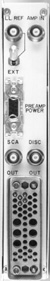
| EXT LLD When the rear-panel-mounted Lower-Level
Reference switch is on Ext, this rear-panel BNC connector accepts the lower-
level biasing (an input of 0 to 10 V on this connector corresponds to
a signal in the range of 0 to +10 V for the lower-level discriminator setting).
Input impedance 2000 W. |
|
ELECTRICAL AND MECHANICAL
|
| Power Required +24 V, 35 mA; 24 V, 25 mA;
+12 V, 115 mA; 12 V, 85 mA. |
Weight
Net 1.3 kg (3.0 lb).
Shipping 2.25 kg (5.0 lb). |
| Dimensions Single-width NIM-standard module
3.43 X 22.13 cm (1.35 X 8.714 in.) per DOE/ER-0457T. |
|
PREAMP POWER
|
| Rear-panel standard ORTEC power connector; Amphenol 17-10090
or equivalent, mates with captive and noncaptive power cords on all standard
ORTEC preamplifiers. |
|
|
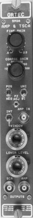
CONTROLS (Amplifier)
|
| COARSE GAIN Six-position switch to select
Coarse Gain factor for amplifier; factors are 10, 20, 50, 100, 200, and
500. |
| FINE GAIN Single-turn potentiometer for direct
reading, continuous adjustment of Fine Gain factor from 0.5 to 2.5. |
| PZ ADJ Front-panel screwdriver adjustment
to match the amplifier shaping to the preamplifier decay time; adjustable
for preamplifier decay times from 30 µs to infinity . Factory set
at 50 µs. |
| SHAPING Three, 3-position printed wiring
board (PWB) switches, easily accessible through the side panel, select
shaping times of 0.5, 1.5, and 3.0 µs. |
| POS/NEG Front-panel toggle switch selects
input circuit for either polarity of input pulses from the preamplifier. |
| UNI-BI Front-panel toggle switch selects
unipolar or bipolar output shape. |
|
CONTROLS (Single-Channel Analyzer)
|
| LOWER LEVEL Front-panel 10-turn potentiometer adjustable
from 0 to +10 V; when the rear-panel LL Ref mode switch is set on Int,
determines the threshold setting for the lower-level discriminator. When
the LL Ref mode switch on the rear panel is in the Ext position, this control
is ineffective. |
| WINDOW 10-turn precision potentiometer on front
panel for adjustment of analyzer window width (0 to 10 V or 0 to 1 V as
selected by an internal jumper. Factory set at 0 to 10 V). |
INT/WINDOW Front-panel toggle switch selects
operating mode.
Window LL sets the baseline level (0 to 10 V) and the
Window control sets the window width between 0 to 1 V or 0 to 10 V.
INT Integral LL sets a single discriminator threshold
(0 to 10 V) and the Window control is disabled. |
| LOWER-LEVEL REFERENCE Toggle switch mounted
on the rear panel selects the source of lower-level bias. Int position
selects front- panel control; Ext selects lower-level bias through rear-panel
connector. |
|
INPUT (Amplifier)
|
| AMP INPUT BNC front- and rear-panel connectors
accept either positive or negative pulses, selectable by front-panel toggle
switch, with rise times in the range from 10 to 650 ns and decay times
from 30 µs to infinity; Zin = 1000 W,
dc-coupled; linear maximum, 2 V; absolute maximum, 20 V. |
|
INPUT (Single-Channel Analyzer)
|
| SCA Internally connected to amplifier output;
impedance level of 1000 W. |
| EXT LLD Input from 0 to 10 V, 2000-W
input impedance; rear-panel connector. |
|
OUTPUT (Amplifier)
|
| AMP Front-panel BNC, Zo <1
W. Short-circuit proof; prompt full-scale linear
range, 0 to +10 V; active filter shaped and dc-restored for unipolar output;
dc level 0 to ±5 mV. |
|
OUTPUT (Single-Channel Analyzer)
|
| SCA OUT Front- and rear-panel BNC connectors
provide NIM standard output nominally +5 V, 500 ns wide; typically 50-W
output impedance. |
| DISC OUT Rear-panel BNC connector provides
NIM standard output, nominally +5 V, 500 ns wide; typically 50-W
output impedance. Output occurs as leading edge of linear input crosses
the window threshold. |
|
|