E94-010 Polarized 3He Target NMR System
Last updated on October 22nd, 1998.
This page describes how to use safely the NMR system to measure the polarization of the polarized target in the best conditions. It should be read by every target operator before taking any shift. For more detailed information and if you have any question, contact Sebastien Incerti. Click on any subject below or simply read the entire page.
Experimental NMR Setup
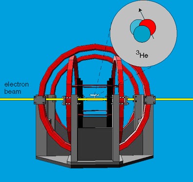
The NMR experimental setup consists of four sets of coils surrounding the target cell :
- The large and small pairs of Helmholtz coils along the horizontal axis and oriented 90 deg from each other. They provide the constant holding field along which the Helium spins remain aligned. It will be swept from 25 G to 32 G up and down during the NMR polarization measurement.
- The pair of RF coils, along the vertical axis, creating the oscillating RF field, during the AFP sweep. At the resonance, the spins will be rotating around the electron beam axis at an angle of 90 deg.
- The pick-up coils pair, aligned along the target cell, and which axis is perpendicular to the beam line. They detect the induced NMR voltage when the spins are rotating around the beam axis (when the RF field is on) and send the signal to the lock-in amplifier in the Counting House. At the resonance, the voltage magnitude is proportional to the target polarization.
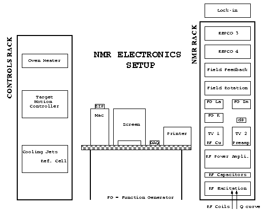
NMR Electronics Setup
This schematic presents you the NMR electronics setup located in the Hall A Counting House. The NMR Rack is located on the right hand side of the Macintosh table, and the Controls rack, on the left side, close to the white board.
- NMR Rack :
from the top to the bottom of the rack, you may locate : the pick-up coils lock-in amplifier, the Kepco 3 power supply providing the current to the large set of coils, the Kepco 4 power supply for the small set of coils, the field feedback box used for the EPR polarization measurement only, the field rotation box, used to get rid of the Kepco glitches generated during the rotation process, the two rotation function generators driving the Kepcos power supplies (one for each Kepco power supply), the rotation function generator driving the rotation box, two TV monitors, the left hand side one showing the RF current circulating in the RF coils and the right hand side one being not in use now, the RF power amplifier producing the RF power, the RF capacitor box, used to amplify the current in the RF coils, and finally the function generator driving the RF power amplifier. An RF attenuator (20 dB) has also been inserted between the RF function generator and the power amplifier. You may note the two BNC cables available at the input of the RF function generator : the RF coils cable or the Q curve cable, which will have to be exchanged if you need to measure the Q factor of the pick-up coils circuit (as will be explained later).
- Controls Rack : contains the oven heater control chassis (oven air flow, oven temperature and heater temperature, in deg Celsius), the target motion controller (with the two red position digital displays), the flow meters of the cooloing jet system (two red digital displays on the bottom left hand side) and the reference cell pressure digital gauge, in the middle, read in psia.
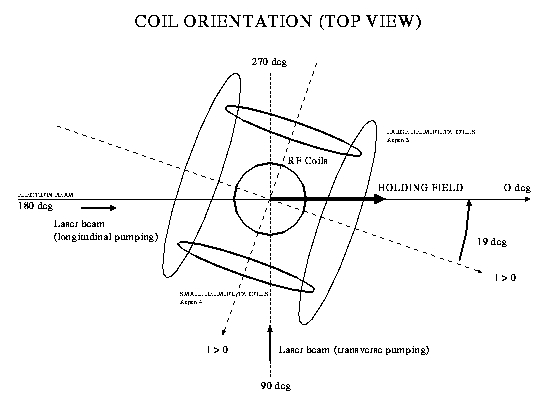
Angle Convention
This top view of the target system in the Hall explains you the way to define the angle between the beam line and the holding magnetic field :
- 0 deg angle : corresponds to the parallel configuration : the holding field is parallel to the incident electron beam momentum (so points downstream). This is the normal field orientation in the parallel configuration, and is also the orientation of the field where you measure the polarization of the target.
- 180 deg angle : corresponds to the antiparallel configuration : the holding field is antiparallel to the incident electron beam momentum (so points upstream)
- 90 deg angle : corresponds to the perpendicular configuration, when the holding field is perpendicular the the electron beam, pointing towards the hadron arm side
- 270 deg angle : corresponds to the perpendicular configuration, when the holding field is perpendicular the the electron beam, pointing towards the electron arm side. This is the normal position of the holding field in the perpendicular configuration.
The schematic also shows you the direction of the field created by each set of Helmholtz coils when their corresponding Kepco power supply displays a positive current (I>0 on the graph).
The Macintosh Personal Computer
A Macintosh Power PC 8100/80AV located in the counting House allows us to control entirely the polarization measurement procedure, using both the NMR and the EPR technics. The Macintosh communicates with the electronics exclusively through the General Purpose Interface Bus (GPIB), using the LabView v4.1 software. It has a memory of 96 Mb, and uses two hard disks (HD1 and HD2+HD3), one of which is split in two units (HD2 and HD3). The LabView programs used for the NMR and the EPR systems are stored in the partition HD3 and the NMR and EPR Data are saved on HD2. HD1 contains the Macintosh operating system and all the application programs.
Opening the NMR Master panel
Before starting any NMR measurement, you must open the NMR Master panel displayed below. To open the panel, simply click with the Mac mouse on the Apple icon located on the upper left corner of the Mac screen, hold the mouse button down to reveal the 'Apple menu', and choose NMR Master. the NMR Master panel should pop up.
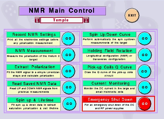
This panel is a self-running Virtual Instrument (Vi), allowing you to choose between ten procedures, each of which is detailed on this page. To start a procedure, simply click on the coresponding circular Go button. You may also quit the Vi by clicking on the Exit button. We describe below in detail each procedure, in the chronological order they should be performed.
The Record NMR Settings panel
Before any NMR measurement, you must fill out the NMR Settings panel and print it. The print out should be kept in the target NMR logbook. Please, do not forget to enter your name in the blue Target Operator window, and the LAST RUN NUMBER in the data taking. Make also sure the target name is the right one. This sheet allows us to keep track of each important setting :
- Controls rack, located close to the whiteboard
- Lock-in amplifier, located above the NMR rack, on the right hand side of the Macintosh
- NMR rack, on the right hand side of the Macintosh
- Lasers Monitor & X terminal, on the small TV monitor below the alarm panel, and on the X terminal, below the spectrometer magnets NMR oscilloscopes, on the counting house control desk on the right hand side of the NMR rack
- RTD X terminal, below tne spectrometer magnets NMR oscilloscopes, on the counting house control desk
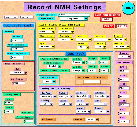
We describe here each setting :
- Controls Rack : the Heater Settings are read on the oven heater controller chassis. The default values indicated should be close to the ones you may read. The Target Position is given by the red digital display on the target motion controller ; it tells us which target is in the beam : reference cell (glass cell with variable pressure), no cell, BeO target, polarized target and position where the polarized target is between the pick-up coils. This is the position where the target should stand if you want to measure the polarization of the target. Therefore, before any NMR measurement, call MCC (7047) and tell them you are about to move the target to its polarization measurement position. Once they agree, move the target to the pick-up coils position. After the measurement, put the target back into the beam position and call MCC back. The Helium Cooling Jets flows are displayed on the bottom red box, on the left of the Reference Cell pressure gauge.
- Lock-In Amplifier (above NMR rack) : due to its location in a quiet corner of the counting house, the settings are pretty hard to check. However, they may be crucial to the analysis of the helium NMR signals. Each setting is indicated by a small green led on the front panel of the lock-in. The phase can be read on the very right hand side display (the third one : for instance, -62.88 deg). Make sure to note carefully its value ! The Offset 1 and Offset 2 selectors should be set to OFF by default, if no yellow 'XY Offs' display appears just below the first two red displays.
- NMR Rack : the NMR Rack contains the two Kepco power suplies (Kepco 3 and Kepco 4) which drive the main Helholtz coils. Kepco 3 drives the large set, and Kepco 4 the small set. They should both be set to Voltage mode and the red switches located close to the black knobs should always be set to off. If not, contact S. Incerti (P:6444). Please, write down the value of the Voltage and the value of the current. The Rotation Box is located in the rack, just below the Field Feedback Box. It should always be turned on ! If not, the Kepco power supplies will not deliver any current ! the RF Current Monitor is a small toroid through which flows the RF current, located in the Hall. Its output is given by an oscilloscope viewed on the RF Current (TV monitor), above the RF preamplifier. When you fill out the form, there is no RF current in the RF coils. The current will appear when you start the AFP sweep, using the NMR Measurement panel. Therefore, you will have to write down by hand on the print out sheet the value displayed on the oscilloscope when you run the NMR Measurement Vi. The Preamplifier (TV monitor) displays the settings of the preamplifier located near the coils in the Hall. During the experiment, the video camera has been removed to prevent any damage. The settings displayed on the Vi have been set by the NMR operator (S. Incerti) and should not be changed . Finally, the RF Circuit box allows you to specify the value of the capacitor introduced in the RF circuit to increase the RF current delivered to the coils. It has been set to 38 nF and should not be changed.
- Lasers Monitor & X terminal : The TV monitor located below the gas alarm panel allows you to look at each laser control box. On the HAC X terminal screen, in the Lasers display area, you can read the current and the temperature of each laser. Enter on the form how many lasers are running (if a laser is running, its current is not zero). In the longitudinal configuration, the longitudinal lasers should be running and the transverse lasers should be off. In the transverse configuration, the longitudinal lasers should be off and the transverse lasers should be running. We have 4 longitudinal lasers and 3 transverse lasers, each of 30 W.
- RTD X terminal : The RTD X-Terminal screen is displayed on HAC, in the Cell Temps display area, on the window entitled : He3Target.adl. Seven RTDs are displayed. Each temperature should be entered on the form.
Once you have filled out the form, simply click on the Print button to print it, and stick it in the target logbook. You will be asked to check if the Mac printer has enough paper (in its lower tray). The Vi will close automatically.
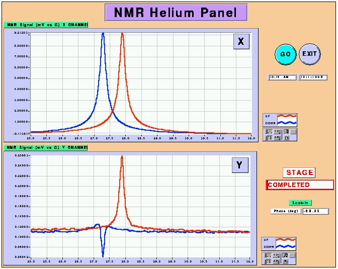
The NMR Measurement panel
This panel should be called after running the NMR Settings panel. It performs the AFP spin sweep of the polarized Helium 3 sample through the resonance. Once again, we remind you that the target must be in the pick-up coils position to perform the measurement. The default settings of the Vi are the following :
- Holding field orientation : 0 deg (downstream) or 180 deg (upstream)
- Range of the sweep : 25 G to 32 G back to 25 G
- Shape of the sweep : up - plateau - down
- Speed of the sweep : 1.2 G/s
- RF Voltage : 2.4 Vrms
- RF Frequency : 91 kHz
They cannot be changed. To launch the sweep, simply click on the Go button. Do not forget to write down on the NMR Settings printout the peak-to-peak voltage displayed on the RF Current monitor when the needle of the power amplifier goes to its optimal value. The Vi displays X and Y readouts of the lock-in. The phase should be set such that the signal is maximum in one channel, and minimum in the other one, as shown below. The UP signal is displayed in red, the DOWN one in blue, as a function of the holding field value. The shift between the up and down value reveals a delay in the coil response. Note the display of the lock-in phase. The X and Y data are automatically saved in the folder :
HD2:NMR Data:Helium
and are stamped with the date and time of the measurement. When you are done, print the screen using the key combination [Apple key]+[P]. A menu will pop-up and confirm to print on the Mac printer. After that, you may press the Exit button to close the Vi.
The Extract Polarization panel
This Vi should be used just after the AFP sweep. It doesn't need any particular tuning. Just run it by clicking on the Go button. You will first be asked if you want to create an R file, from previously saved X and Y data. R is simply the square root of the sum of the squares of X and of Y. Just choose No unless you have been notified to. Another window opens to ask you to choose your data file. Simply go to :
HD2:NMR Data:Helium
and choose the file (X or Y) corresponding to your last measurement and having the largest amplitude. The name of your data file will be displayed in the Data File window for confirmation. Then the Vi will start to fit the UP and DOWN signals. The result of the fit should appear after a few minutes. The Vi will give you the value of the polarization, using both calibration methods : the NMR Water calibration and the EPR calibration. The fitting function is the square root of a Lorentzian with a linear background and has five free parameters : height of the signal, full width at middle height, resonance field, background slope and background constant. Also are displayed the reduced chi square and the correlation matrix for the UP and DOWN signal.
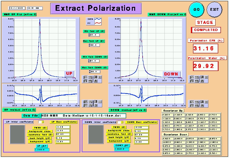
Once again, print the display when you get the polarization values, using the [Apple key]+[P] combination. Press the Exit button to quit. You can also press again the Go button if you want to change the range of the fit (Min Field Up, Max Field Down, idem for DOWN) set by default to 25 G and 32 G. You may also specify your own guessed values of the inital fitting parameters in the grey arrays ; if so, do not forget to switch the two yellow buttons to the UP initial coefficients and DOWN initial coefficients positions.
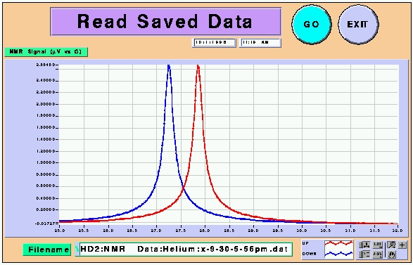
The Read Saved NMR Data panel
This Vi should be used if you simply need to check the content of a saved NMR data file. Simply press the Go button to run the Vi ; a window will pop-up asking you to choose a data file. We remind you that the NMR data files are located in :
HD2:NMR Data:Helium
The name of your data file will be displayed in the Data File window for confirmation. When done, you can print the window using the key combination and quit the Vi by pressing the Exit button.
The Spin up & Lifetime panel
This Vi allows you to fit spin up or spin down. Spin up data are used to predict the saturation value of the target polarization, and spin down data allow us to extract the lifetime of the cell.
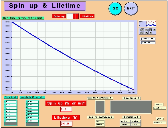
First, switch the red button to Spin up to fit spin up data or to Lifetime to fit spin down data. Then, simply enter the Time values (in minutes) in the first left hand side array named 'Time' and the corresponding Amplitude or Polarization values in the 'Amplitude' array. Then press GO to run the Vi. Your data points and the fit will be displayed together, and you will get an estimation of the maximum polarization the target can reach (Spin up window) or the cell lifetime (Lifetime window).
The Spin Up/Down Curve panel
This Vi should be used if you are asked to draw the spin-up/down curve of the target. It performs several AFP sweeps using the NMR Measurement Vi, their total number being specified by the control button 'Total number of sweeps' regularly spaced in time, as specified by the 'Delay between ramps (min)' control. When you press Go, it will display the evolution in time of the height of the R UP and DOWN lock-in signals. We remind you that the target must remain between the pick-up coils if you decide to run that Vi. Once done, you may print it with [Apple]+[P] and quit by pressing Exit.
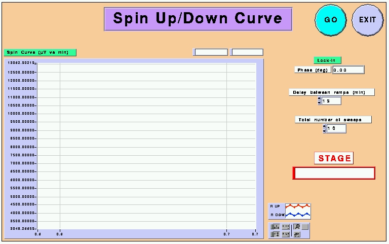
The spin-up curves are saved in the folder :
HD2:NMR Data:Spin_up
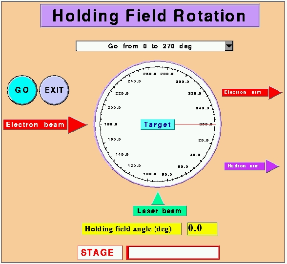
The Holding Field Rotation panel
The field rotation panel should be used to switch from the parallel (perpendicular) to the transverse (parallel) configuration. Refering to the angle convention, 0 deg points downstream and 270 deg points at 90 deg from 0 deg on the electron arm side. Before running the Vi, you need to select the rotation you need to perform :
- Rotation from Parallel to Perpendicular : choose Go from 0 to 270 deg
- Rotation from Perpendicular to Parallel : choose Return to 0 from 270 deg
When you have made your choice, simply press the Go button to launch the Vi. You will be asked to check that the Rotation Function Generator (Wavetek, with the sticker FG R) is not on Standby mode (yellow steady led). If it is on Standby mode, simply press the horizontal arrow keys on the right to go to the square burst shape. Than the Vi starts. The process is slow and can take up to 15 minutes. You will be able to follow the field rotation on the virtual compass. When done, simply click on the Exit button to quit.
WARNING ! : you must absolutely be in the PARALLEL configuration to measure the polarization of the target using the NMR method !!
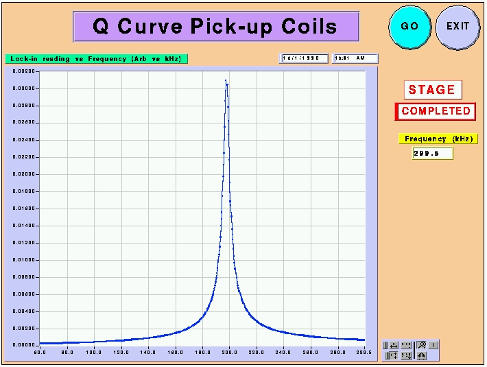
The Pick-up Coils Q Curve panel
This Vi allows you to check the response of the pick-up coils circuit using a small excitation loop, glued on the side of the RF coils mount. When you run the Vi by pressing the Go button, you will be asked to disconnect the RF coils cable coming out of the RF function generator (Hewlett Packard with the RF Excitation sticker) and to connect the Q curve cable, going to the small loop. Then the Vi will sweep the excitation frequency and the lock-in will read the pick-up coils response. The sweep process is slow and may take as much as 20 minutes. The frequency is displayed in the Frequency window, in kHz. When done, the resonance curve will appear on the screen and will be saved in the directory :
HD2:NMR Data:Q Curves
When done, do not forget to switch the cables back ! You may print the window using the key combination [Apple]+[P] and quit using the Exit button.
The Current Monitoring panel
The Current Monitoring Vi is used to check the values of the current circulating in the Helmholtz coils. For now, only the large coils current can be monitored. An amperemeter is connected to the large coils in the Hall and is read by a GPIB-ENET box. If you run the Vi by pressing the Go button, the GPIB-ENET box will transmit by default 10 values of the current as shown below. You may change the number of values read using the 'Number of measurements' control.
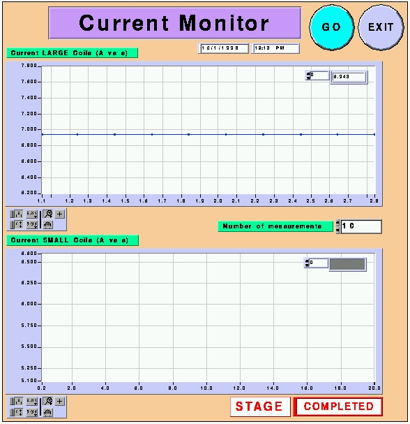
When done, the data will be saved in the directory :
HD2:NMR Data:Current
You may print the window using the key combination [Apple]+[P] and quit using the Exit button.
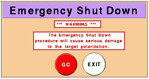
The Emergency Shut Down panel
The Emergency Show Down Vi should be used only in case of extreme emergency. By pressing the Go button, you will turn off the RF excitation field, and kill the main holding field. It should be use only to turn off the current in the main Helmholz coils and in the RF coils, when intervention on the coils is required. The target operator should be aware that the polarization of the target may be dramatically damaged if this Vi is used. Press the Exit button if you decide not to run that Vi at the very last minute.
Quitting the NMR Master panel
Simply go back to the NMR MAster panel and click on the small red button displayed near the upper left hand corner of the Vi. The Vi will stop and you can close the window by clicking on the small grey square in the very upper left corner of the window.
To Summarize : Basic Procedures
1 - NMR MEASUREMENT
A NMR mesurement can be performed only in the LONGITUDINAL configuration. NMR measurements are usually performed :
- before rotating the holding field (longitudinal to transverse or transverse to longitudinal).
- when changing the momentum settings in the spectrometer magnets.
To perform a measurement :
- Call MCC and tell them you want to move the target to the pick-up coils position.
- Move the target down to the value corresponding to the pick-up coils position given by the small table close to the position displays on the motion controller. The target is moved using the UP/DOWN switch and the FAST/SLOW switch (SLOW for precise adjustment of the position). The LOCAL/REMOTE switch should be set to local to allow the motion. Set it back to REMOTE when you have moved the target.
- Open the NMR Master panel.
- Run the Record NMR Settings panel and keep the printout.
- Print the RTDs screen displayed on HAC.
- Run the NMR Measurement panel and print it.
- Run the Extract Polarization panel and print it.
- Move the target back to its beam position (using the LOCAL, UP and FAST/SLOW switches on the target motion controller) and call MCC back.
- Put all the printouts in the target notebook and staple them.
2 - FIELD ROTATION
- Rotating from Parallel to Perpendicular
- Before the rotation, turn off the 4 longitudinal lasers using the lasers screen on HAC.
- Open the NMR Master panel.
- Run the NMR Rotation panel.
- Choose Rotate from 0 deg to 270 deg.
- After the rotation, turn on the 3 transverse lasers, using the lasers screen on HAC.
- Check the lasers settings on the TV monitor above the EPR rack.
.
- Rotating from Perpendicular to Parallel
- Before the rotation, turn off the 3 transverse lasers using the lasers screen on HAC.
- Open the NMR Master panel.
- Run the NMR Rotation panel.
- Choose Return to 0 deg from 270 deg.
- After the rotation, turn on the 4 longitudinal lasers, using the lasers screen on HAC.
- Check the lasers settings on the TV monitor above the EPR rack.
.
Back
to E94-010 homepage