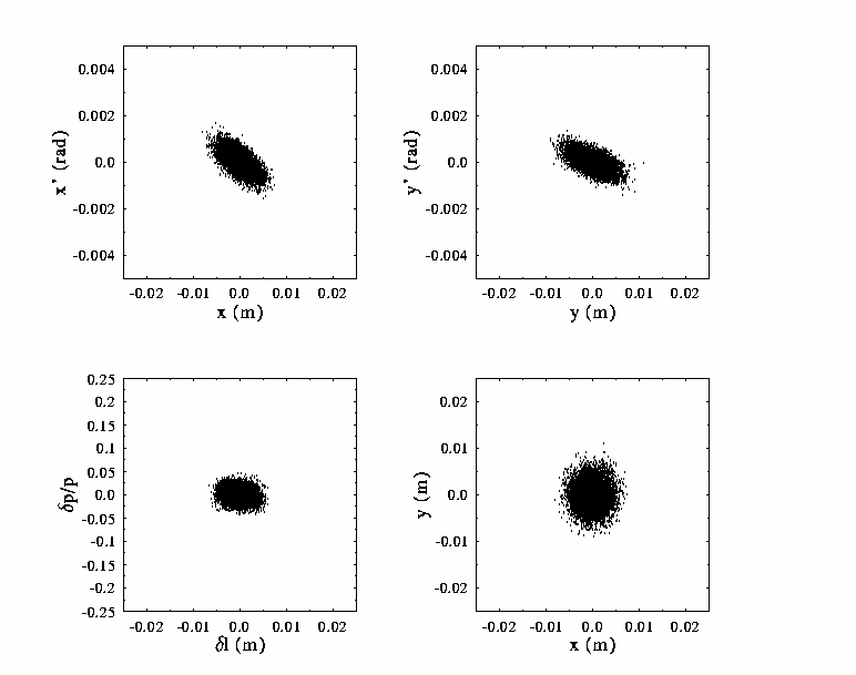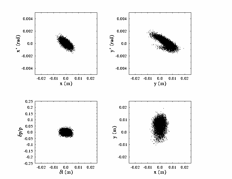

A simulation of the energy recovery process has been performed using DIMAD. An initial 6 sigma/6 dimensional phase space is gaussian-loaded with 10000 particles at the center of the wiggler using design beam parameters, the design rms emittance, and a 1% rms momentum spread. The resulting population is tracked through the system to the 10 MeV extraction point following the cryomodule.


The above figures show the transverse and longitudinal phase spaces and the transverse configuration space. The first set of plots illustrates the the result of ideal transport, the second set shows the same information with a 1 mm initial vertical missteering of the beam. We now observe a significant growth and distortion of the vertical phase space, due to the aforementioned T336 aberration and chromatic variation of the vertical phase advance with momentum. The total vertical spot size nearly doubles due to the errors. Note however, that FEL operational constraints require steering to an orbit error some 30 times smaller to insure overlap of the electron beam and optical mode; under these circumstances, the resulting vertical phase space distortion and spots size growth will be negligible. Note as well that the wiggler center is at a point with very small beam envelope; a 1 mm orbit error at this location is in fact a large offset, which will grow to order 1 cm downstream. An offset of this magnitude can be observed in the y centroid in the above figures. Such errors will be suppressed as a part of normal orbit correction, thereby limiting vertical spot growth from this mechanism to low levels.
Similar experiments have been performed missteering the
beam in angle at the wiggler. Computations were repeated using
beams of equal and unequal horizontal and vertical emittance
(both horizontal greater than vertical and the converse). In
all cases, the results were similar to those presented above,
indicating that chromatic, geometric, and coupling aberrations
do not seriously degrade the system performance.
| Project Overview | |
| System Design Process | |
| Application of Process to High Power IR FEL | |
| Description of Solution | |
| System Performance | |
| A. Linear Optics | |
| B. Aberration Analysis | |
| C. Chromatic Performance | |
| D. Geometric Performance | |
| **you are here! ** | E. Simulation of Energy Recovery |
| **the next link is | Error Studies |
| Upgrade Scenarios | |
| | |
| Go to The FODOmat's FEL Page | |
Last modified: 10 March 1997
http://www.jlab.org/~douglas/
is maintained by: douglas@jlab.org