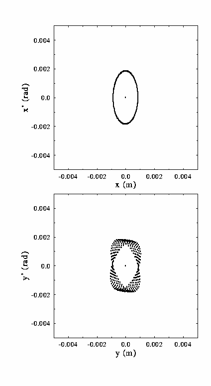
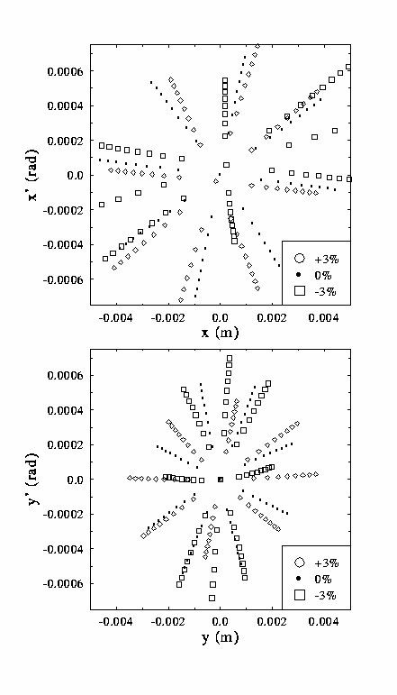
| Geometric aberration analysis: phase space from cryomodule to wiggler in 1% momentum steps from -3% to +3%. | Geometric aberration analysis: phase space from wiggler to cryomodule in 1% momentum steps from -3% to +3%. | |
|---|---|---|
|
| |
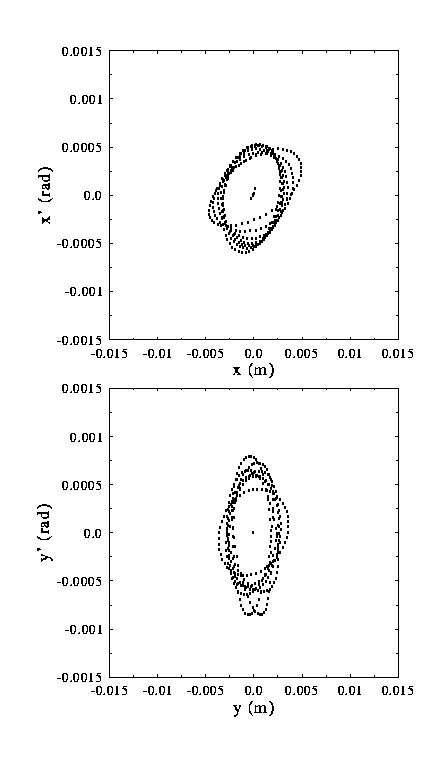
The geometric aberration performance of the transport system has been studied through use of the DIMAD "line geometric aberrations" operation. A specified ellipse is loaded with numerous particles, which are then traced through a portion of the system to provide an image phase space. A beam ellipse is fitted to the image phase space to obtain average betatron functions and emittance values. Individual particle emittances are then computed by assigning to each particle the average betatron function and constraining it to lie on an ellipse similar to, but possibly at a different emittance than, that defined by the average. The resulting emittance deviations quantify the level of phase space distortion encountered.
Studies conducted at 10 times the design emittance (equivalent
to an normalized rms emittance of 130 mm-mrad) show only modest
phase space distortion (delta epsilon/epsion <~0.25) over
the full momentum acceptance of the system. Individual phase
spaces injected at design beam envelope values and propagated
at momentum offsets in 1% intervals over the full momentum
acceptance show little visible distortion and only modest
variation in beam phase spaces. Results for the cryomodule
to wiggler transport are shown in the first of the following
figures; those for the wiggler to reinjection point transport
are presented in the second of the following figures.
| Geometric aberration analysis: phase space from cryomodule to wiggler in 1% momentum steps from -3% to +3%. | Geometric aberration analysis: phase space from wiggler to cryomodule in 1% momentum steps from -3% to +3%. | |
|---|---|---|

|

| |
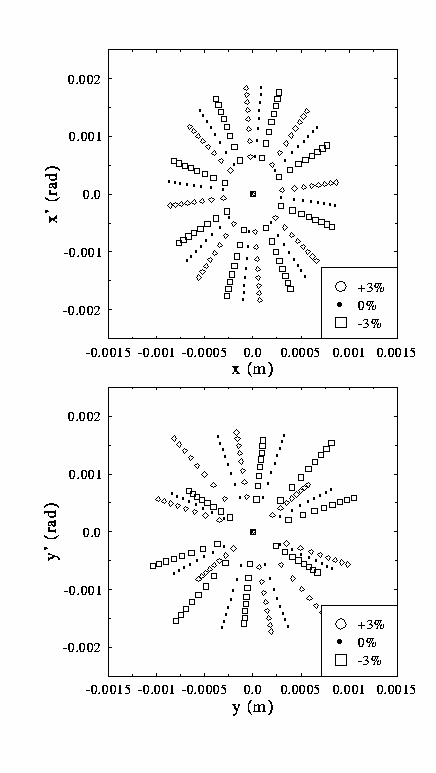
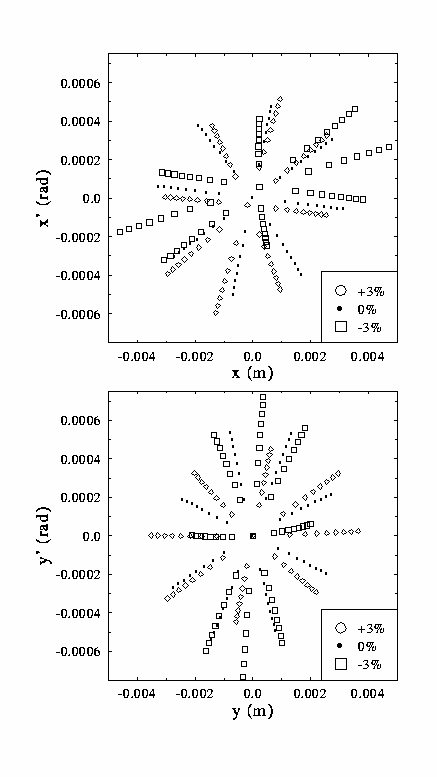
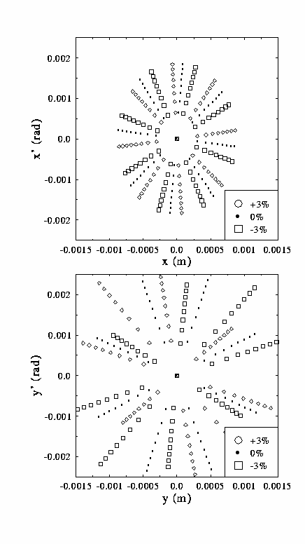
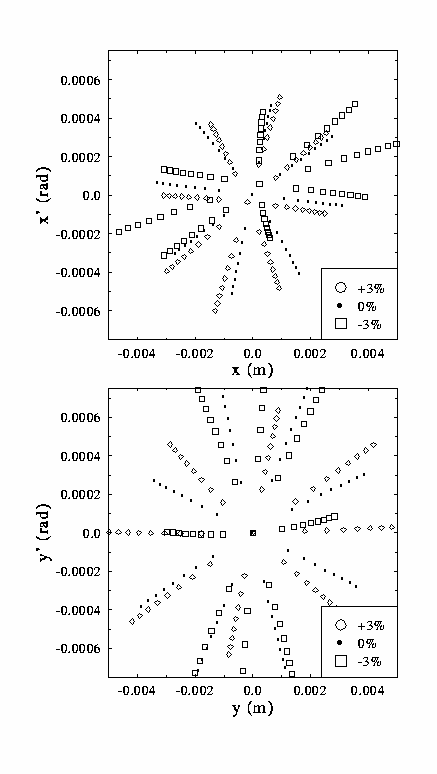
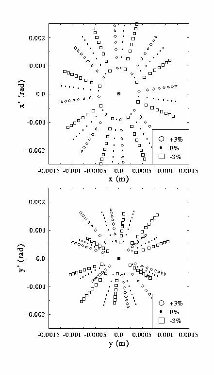
The above graphs indicate that geometric aberrations impose little phase space distortion on the beam. An alternative presentation of geometric data demonstrate that the beam experiences little betatron phase variation with amplitude as well. The following figures present the results of a computation in which particles are loaded in uniform phase intervals on initially matched beam ellipses of various emittances, and tracked through portions of the transport at momentum offsets of -3%, 0%, and +3%. In the specific cases presented, tracking was done from cryomodule to wiggler (left hand column) and from wiggler to reinjection point (right hand column). Design beam envelope values were used to populate phase ellipses at emittances of 0.2 to 1.6 mm-mrad in 0.2 mm-mrad increments, at eight uniformly spaced initial phase offsets. The maximum emittance used is equivalent to ten times the design emittance value.
Following tracking through the beam line, the variation of beam
envelopes with momentum and the variation of phase with momentum
(manifested by the failure of circled, squared and dotted lines
to overlap) are evident. These were observed in the previous
computation as well as in the study of chromatic behavior, and
should not adversely affect machine performance. Inasmuch as
the lines remain straight for all phases and emittances, we
conclude that no significant variation of betatron phase with amplitude
arises, confirming that the geometric performance of this beamline is
acceptable to at least 10 times the nominal emittance. As this result
holds for equal and unequal emittance, we conclude that the system
exhibits little inherent horizontal/vertical coupling.
| Geometric aberration analysis from cryomodule to wiggler: tracking at -3%, 0%, and +3% momentum offsets of test rays uniformly distributed in betatron phase on design ellipses of 0.2 to 1.6 mm-mrad emittance, with equal horizontal and vertical emittances | Geometric aberration analysis from wiggler to cryomodule: tracking at -3%, 0%, and +3% momentum offsets of test rays uniformly distributed in betatron phase on design ellipses of 0.2 to 1.6 mm-mrad emittance, with equal horizontal and vertical emittances. | |
|---|---|---|
|
| |
| Geometric aberration analysis from cryomodule to wiggler: similar tracking with horizontal emittances of 0.2 to 1.6 mm-mrad and vertical emittance equal to twice the horizontal. | Geometric aberration analysis from wiggler to cryomodule: similar tracking with horizontal emittances of 0.2 to 1.6 mm-mrad and vertical emittance equal to twice the horizontal. | |
|---|---|---|
|
| |
| Geometric aberration analysis from cryomodule to wiggler: similar tracking with horizontal emittances of 0.4 to 3.2 mm-mrad and vertical emittance equal to half the horizontal. | Geometric aberration analysis from wiggler to cryomodule: similar tracking with horizontal emittances of 0.4 to 3.2 mm-mrad and vertical emittance equal to half the horizontal. | |
|---|---|---|
|
| |
| Project Overview | |
| System Design Process | |
| Application of Process to High Power IR FEL | |
| Description of Solution | |
| System Performance | |
| A. Linear Optics | |
| B. Aberration Analysis | |
| C. Chromatic Performance | |
| **you are here! ** | D. Geometric Performance |
| **the next link is | E. Simulation of Energy Recovery |
| Error Studies | |
| Upgrade Scenarios | |
| | |
| Go to The FODOmat's FEL Page | |
Last modified: 10 March 1997
http://www.jlab.org/~douglas/
is maintained by: douglas@jlab.org