

Many analytically established error tolerances have been confirmed using numerical methods. Simulation indicates that a baseline array of beam position/profile profile monitors and correctors placed roughly every quarter betatron wavelength in phase advance will allow machine operation in the presence of all anticipated errors and will not lead to intolerable beam quality degradation.
A DIMAD model of the wiggler to reinjection transport was constructed and used to study effects of error levels consistent with the analytically derived error budget. An "ensemble" of ten randomly distributed sets of alignment and powering errors was generated, and the beamline performance modeled when the errors were imposed. Correction of on-momentum orbit errors only was then implemented, and the performance analysis repeated. In this analysis, four criteria for machine and beam behavior were examined:
| element type |
rms xin (mm) |
rms xout (mm) |
rms yin (mm) |
rms yout (mm) |
rms z (mm) | rms roll (mrad) |
rms excitation error (ppt) |
|---|---|---|---|---|---|---|---|
| quadrupoles - main - trim | 0.5 0.5 | 0.5 0.5 |
0.5 0.5 | 0.5 0.5 |
5 5 | 1 1 | 1 2.5 |
| BPMs | 0.5 | - | 0.5 | - | 5 | 0 | - |
| sextupoles | 1 | 1 | 1 | 1 | 5 | 1 | 2.5 |
| dipoles - injection/extraction - optical cavity - reverse bends |
1 1 1 | 1 1 1 |
1 1 1 | 1 1 1 |
5 5 5 | 1 1 1 | 1 1 1 |
Conclusions and comments are summarized at the end of this section.
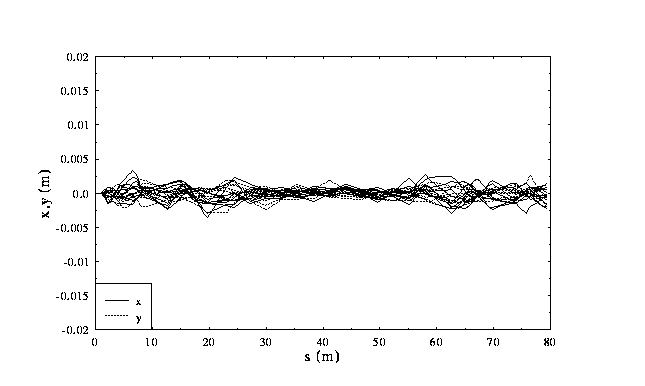
The figure presented below displays horizontal and vertical central orbits for the sampled ten random error sets ("ten seeds") before and after correction. All orbits remain within the 2 inch vacuum chamber before correction. All orbits are significantly improved by the correction process.

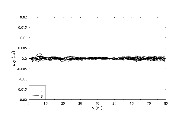
We have found that the rms residual orbit tracks the rms BPM misalignment down to submillimeter levels (see the following plot, which displays corrected orbits with an rms BPM misalignment of 1 mm rather than the 0.5 mm used in the preceding figures). We plan to rigidly fixture BPMs to adjacent quadrupoles (which will be aligned to 500 microns, rms) and calibrate the BPM by beam centering in the quad. This will provide BPM alignment to well below 1 mm rms, which in turn will allow orbit correction to submillimeter rms residuals, adequate for machine operation.
Off Momentum Orbits/Dispersions/Momentum Compaction -
The figures below show plots of off-momentum orbits at
+/-3% for ten
random error sets before and after orbit correction. In this case,
the correction is done for the on-momentum central orbit only. We
find that simple correction of just the on-momentum central orbit
leads to generally adequate machine performance; the off-momentum
orbits track the corresponding on-momentum orbits, indicating that
the correction is more or less local. If ongoing studies indicate
the need to do so, the off-momentum orbits can be separately
constrained during the orbit correction process as well, and/or
dispersion correction can be activated during or after orbit
correction.


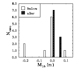
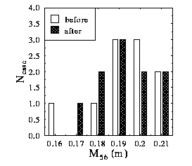
Histograms of dispersions and momentum compaction (specifically,
M16, M36,
and M56 from wiggler to reinjection point)
for each of the ten random seeds studied, before and after
correction of the on-momentum central orbit, are given below.
Before correction, horizontal dispersion and momentum compaction
are fairly near design values, but spurious
vertical dispersion can become rather large (up to ~0.3 m).
This is probably due to the fact that this type of lattice tends
to have large T336, T346,
T436, and/or T446
values. Vertical quadrupole misalignments will cause angular
kicks that couple to these aberrations and thereby generate
large effective vertical dispersion. Localized correction of
the on-momentum orbit will compensate such effects at their
source; this is seen in the figure, where we note that all
dispersive matrix elements return to near-design values following
orbit correction.
 |
 |
 |
Momentum Scans of Orbit and Betatron Properties -
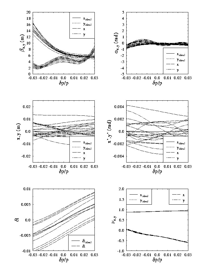
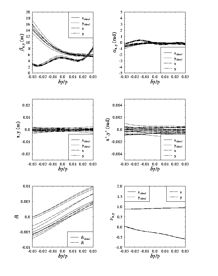
The next graphs present the results of momentum scans of beam position, angle, and
lattice functions at the reinjection point, and path length variation and
phase advance from wiggler to reinjection point, before and after correction
of the on-momentum central orbit. The orbit correction process significantly
reduces the final position and angular offsets and their variation with
momentum. This is consistent with the above discussion. The seed-dependent
scatter in path length is well within the range of compensation available
in the machine; the momentum dependence is nearly ideal. Beam envelope
functions exhibit only moderate dependence on momentum errors both on and off
momentum, even before correction. They are nearly ideal after correction.
The figure below displays the relative emittance distortion vs.
momentum for each of 10 random seeds, before and after correction of the on-
momentum central orbit. A beam with 10 times the design geometric emittance of
0.16 mm-mrad (a 13 mm-mrad normalized emittance at 42 MeV)
was used in the DIMAD "line geometric aberrations" operation to evaluate
the phase space distortion. Performance is acceptable in all cases, and approaches
the ideal machine behavior after correction. Results are similar if unequal emittances
(horizontal twice vertical or vice-versa) are used.

Horizontal/vertical coupling about a specified orbit can be computed using the DIMAD "rmatrix" operation, which evaluates the linear transfer matrix about the orbit of interest and evaluates the determinants of the various transverse sub- blocks. The following tables present the results of this process for each random distribution studied, before and after correction of the central orbit. Before correction, the H/V coupling parameters DET B and DET C are small; after correction they are vanishingly small. The transport system is therefore not expected to experience inherent coupling problems. Any such difficulties will be due to magnetic field errors and/or coupling in the RF cavities, both of which will be evaluated in future simulations.
| Submatrix Determinant Before Correction | Submatrix Determinant After Correction | |||||||||||||||||||||||||||||||||||||||||||||||||||||||||||||||||||||||||||||||||||||||||||||||||||||
|---|---|---|---|---|---|---|---|---|---|---|---|---|---|---|---|---|---|---|---|---|---|---|---|---|---|---|---|---|---|---|---|---|---|---|---|---|---|---|---|---|---|---|---|---|---|---|---|---|---|---|---|---|---|---|---|---|---|---|---|---|---|---|---|---|---|---|---|---|---|---|---|---|---|---|---|---|---|---|---|---|---|---|---|---|---|---|---|---|---|---|---|---|---|---|---|---|---|---|---|---|---|---|
|
|
| ||||||||||||||||||||||||||||||||||||||||||||||||||||||||||||||||||||||||||||||||||||||||||||||||||||
The results detailed above indicate that machine performance
is acceptable for errors consistent with the error budget.
The simulation effort is ongoing. Over the next months, the
model will be extended to include magnetic inhomogeneities,
perturbations of pi-bend alignment and excitation, nonlinearities
in the wiggler, and a more accurate cavity transformation
(including H/V coupling and chromatic effects). Machine
parameter sensitivities to individual errors, as well as global
response to multiple errors, will be investigated. Activities
will then shift to modeling of commissioning and operational
processes such as alternate orbit correction algorithms,
dispersion/momentum compaction adjustment, lattice/beam phase
space matching, error resolution and correction of other
lattice properties. A schedule of projected activities is given
elsewhere.
| Project Overview | |
| System Design Process | |
| Application of Process to High Power IR FEL | |
| Description of Solution | |
| System Performance | |
| Error Studies | |
| A. Overview | |
| B. Analytic Studies | |
| C. Error Budget | |
| **you are here! ** | D. Simulation Results |
| **the next link is | Upgrade Scenarios |
| | |
| Go to The FODOmat's FEL Page | |
Last modified: 25 March 1997
http://www.jlab.org/~douglas/
is maintained by: douglas@jlab.org