Appendix D LSOP for CLAS Calibration Lasers
D.1 Detectors and Environment
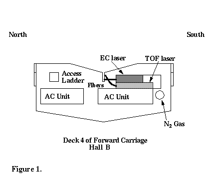
The the highest level of the forward carriage in Hall B at Jefferson Lab contains two identical class IIIb lasers used for calibrating equipment for the CLAS detector. The lasers are used to provide light sources for photomultiplier tubes of the CLAS Time-of-Flight (TOF) and calorimeter systems. The locations of the lasers on the Forward Carriage are shown schematically in Figure 1. Three additional lasers for calibration of the TOF scintillators are located on the north Clam Shell, south Clam Shell and Space Frame. All laser setups are similar, so the same precautions must be taken for each.This Laser Standard Operating Procedure (LSOP) gives a description of the lasers, the hazards present, requirements for personnel and procedures for operation.

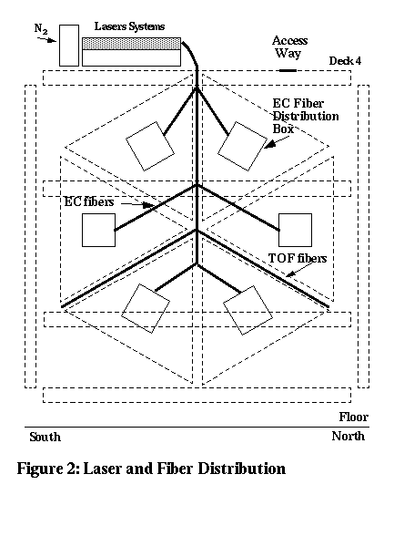
The distribution of fibers for both systems is shown in Figure 2.

D.2 Personnel
The lasers may only be operated by personnel which have
- Completed a laser safety course administered by the safety officers at CEBAF.
- Read the Laser Safety section of the EH&S Manual (6410).
- Read this document.
- Completed and passed an ophthalmological exam which has been reviewed and approved by the CEBAF occupational health physician.
- Sign list of authorized operators
CEBAF personnel or outside visitors, who have not completed the required training, may enter the laser control area under the following conditions:
D.3 Laser
Table 1 lists the characteristics of the Laser Photonics LN203C Nitrogen laser.
D.4 Hazards
Class 1 eyesafe laser conditions exist except during alignment procedures. During alignment procedures, the primary beam hazard associated with class IIIb lasers consists of eye injury caused by viewing the beam either directly or by specular reflection. 99% of the laser light (337 nm) entering the eye is absorbed in the cornea, aqueous and lens. The primary adverse effect from accidental viewing is the production of cataracts. To minimize the laser beam hazard associated with alignment procedures,
The following non-beam hazards exist:
- trip/fall: access to the CLAS nitrogen lasers is limited to an extension ladder. To minimize hazards associated with the use of the ladder:
The ladder must be tied off securely
All personnel must wear safety shoes
One person on the ladder at a time
Nothing is to carried up the ladder. Anything that is to be brought up to the laser work area must be lifted up. Small items can be lifted with a rope.
- bump hazard: To minimize the bump hazard associated with the use of the extension ladder, post danger sign on the ladder noting the hazard and the requirement for a hard hat.
- electric shock: If interlocks are bypassed and high voltage is exposed, there is potential for electric shock. No interlocks are to be bypassed, except by qualified service representatives.
- Fire: a portable fire extinguisher is located in the work area
- Lighting: Most of the emergency lighting for the Hall is located at lower levels and would not be of benefit in the event of a power outage; a standby flashlight is needed.
- Sudden release of energy from cylinder: N2 cylinder must be secured.
D.5 Laser Environment
The location of the LN203C nitrogen lasers is shown in Figure 1. Beam height is approximately 3' above the floor. During normal operation, the laser beam is extracted via a fiber bundle array 1 . These measures prevent unintentional interception of the beam, either directly or by specular reflection. Under special circumstances, detailed below, the laser beam is exposed, and precautionary measures must be taken. The laser light is confined to the Rf-shielding box except during alignment. During alignment, the light is confined by draping a laser shroud over the end of the plexiglass fiber-optic box. Before laser work begins, personnel should make sure that they have a clear path to an exit.
D.6 Remote Control and Operation
The laser can be remotely controlled during routine operation by using specifically designed circuits 2 for the laser. The remote functions including power, pulse rate, enable and disable functions which can be used to automatically shut down operation in case of emergency. An emission time delay is built into the remote control: the yellow beacon energizes when the laser power is turned on, and lasing is delayed by 5 minutes. Once the laser yellow beacon is energized, goggles must be worn.
D.7 Procedures
In this section we review the various procedures that are required to operate the laser. Hazards are least likely to occur during normal operation. During maintenance and alignment, the laser box is open and beam and non-beam hazards are present. The manual for the LN203C laser details installation (Section III), normal operation (Section IV), maintenance (Section V) and trouble shooting (Section VI) of the laser.
When working with the lasers, the personnel must not wear jewelry or clothing which presents a specular reflection hazard. Protective eye wear must be worn with a minimum optical density OD = 1.4 at 337 nm (see Section 7 for the required eye wear). Safety UV-absorbing glasses that meet this requirement are available in the immediate area.
D.8 Maintenance and Initial Alignment
In this case the rf-shielding box is open, the on/off switch is activated, the N2 gas flow rate is adjusted, and the warm-up period initiated. To prevent optical hazards the beam stop should remain closed for this operation except during the initial alignment period. Standard electrical hazard prevention procedures should be followed. To minimize optical hazards, no one will be allowed in the laser control area except trained and qualified personnel who are wearing UV-absorbing safety glasses (see Section 7).
D.9 Scintillator Calibration (Class 1 Conditions)
The laser beams are directed to fiber bundle arrays at the exit of the RF-shielding boxes. The fibers in the bundle are connected to the TOF scintillators or directed to scintillators on the calorimeters Under these circumstances, the lasers shall be considered to pose a Class 1 hazard, as no portion of the beam is exposed.
D.10 Controls
The laser control area will be posted with a danger sign describing the tests being conducted. Figure 1 will be also be posted to indicate the laser control area. The key which turns the laser on shall be kept separate when the laser is not in use, to avoid unintentionally enabling operation. Eyewear is provided and shall be used during maintenance, alignment and any activity which allows viewing of the laser beam. A high voltage safety cover interlock is located on the rear panel of the laser. Removal of the top access panel is required for servicing and will automatically break the interlock. Any interlock interruption will require the high voltage enable switch to be re-engaged to resume operation.
D.11 MPE Calculations
We calculate the optical density, D , of protective eye wear required for laser operation, assuming the laser is continuous. The optical density is given in terms of the radiant exposure, H, and maximum permissible exposure, MPE, by


where a is the limiting aperture (1 mm), f is the maximum operating frequency (50 Hz), Ep is the maximum energy per pulse (100 mJ) and N is the number of pulses (frequency times observation time). With these parameters we calculate that

For an observation time of 10 s, N = 500, D = 0.8. For an observation time of 1 minute, N = 3000, D
 = 1.4.
Next, an MPE was calculated using the pulse width as exposure time by Dr. John Leonowich, a consultant for CEBAF. 3 This calculation yielded a required O.D. of 1.23. We use the more conservative estimate of 1.4.
D.12 Authorized Personnel
The following personnel are trained and qualified to operate the lasers in Hall B:
No other personnel shall be added to the above list without authorization by Elton Smith.

