http://www.jlab.org/~douglas/FEL/technote/JLABTN01043.pdf , for your viewing pleasure, we attach a single result:
Highlights:
The first 100 kW klystron for the upgrade injector was successfully
tested to 85 kW this week.
This is more power than is needed to supply the required 10 mA of beam
current. The vendor expects the tube to top out at
120 kW.
Management:
We are spending time carefully analyzing the cost performance data
as we prepare for close-out of the Phase 1 project by
Sept. 30. We are ensuring that the total project costs do not
exceed the project budget of $9,029k. We are looking at the
remaining obligations on Phase 1 accounts to make sure that they can
all be costed before the cost close-out on Dec. 1. We
are expecting the close-out of the August expenses early next week
so that these data can be included in our analysis.
Potential cost and schedule variances by WBS element are being analyzed.
The project monthly financial and technical reports for July 2001 were
distributed to the DOE and DOD contract monitors
today.
Draft presentations were prepared for the annual DOE/SURA review of
Jefferson Labs Science and Technology which is
scheduled for Sept. 24-25th.
A CRADA with STI Optronics for the design and analysis of compact ,
permanent magnet recirculation magnets for energy
recovered linacs was sent through the lab management chain for sign-off
this week. Preliminary discussions were opened up
with AES, Inc. for negotiation of a CRADA to support an SBIR grant
that AES recently secured to begin the development of
a 100 mA injector based on the IR Demo dc photogun.
A draft budget request was prepared for the Commonwealth of Virginia
to support the upcoming request (Oct. 12th) for input
for the state 2002-2003 budget. The Virginia budget allocation
over the last 4 years has supported the FEL operations
budget and we look forward to and appreciate continued state support
of the FEL program at Jefferson Lab.
WBS 3 (Beam Physics):
Field analysis & certification of the GY performance was completed
and documented (JLAB-TN-01-042, at
http://www.jlab.org/~douglas/FELupgrade/technote/JLABTN01042.pdf)
A preliminary energy recovery dump design was developed and sent into
engineering. See:
http://www.jlab.org/~tennant/TN-01-038.doc
; interferences are being resolved and diagnostic layout worked up.
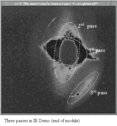
The recent beam transport experiment to test 3-pass operation with the
Demo was documented:
http://www.jlab.org/~douglas/FEL/technote/JLABTN01043.pdf
, for your viewing pleasure, we attach a single result:
WBS 4 (Injector):
Continued work on the shield door test set up. The cathode stalk
subassembly is in brazing. Initial design of the gun stand and
ceramic stack removal cart is done. The hat flange assembly was
completed by the shop. A schedule was set with W&M for
implanting the cathode ball and support tube.
Gun HVPS - Design of the tank and holders for the stacks continue.
WBS 5(SRF):
Completion of the first production 7-cell cavity should occur next
week. (Helium vessel and end groups welded). This
assembly will allow us to determine if HOM coupling will be adequate
for the FEL upgrade cryomodule and will also conclude
the development of the assembly procedures (if successful).
WBS 6 (RF):
Zone 3 - The Filament and Mod Anode board tests were successfully completed.
Testing of interlocks is progressing. The 5
watt pre-amplifiers and their power supply are being installed.
High voltage to the klystrons is expected next week.
Zone 4 - Progress was made this week in getting RF Control Modules calibrated and then returned to the zone.
Injector HPA- First Article klystron tests are scheduled for next week.
The first klystron has already successfully operated to
85 kW and they expect to run it above 120 kW. The factory's HVPS
is being modified for additional power. Low power S
parameter tests were made and plotted for the 100 kW circulators.
This report is being forwarded to the vendor for
suggestions of how to tune the circulators for optimal performance.
Injector HVPS - Design work continues on the upgrade of the HVPS's.
The Main Circuit Breakers, Contactors, SCR Controllers, 12 Pulse Transformers,
Rectifier Assemblies, and Inductors have
been specified, ordered, and many have already been received.
Modeling of the power circuit, crowbar, and klystron
continues for best noise and stability performance.
WBS 8 (Instrumentation):
A new combination amplifier/driver board is in the prototype stages.
The testing on the timing/delay board is complete. It is
installed and working as expected.
The SF6 chassis has been upgraded and the readout is now available in
EPICS. Documentation on this chassis is being
updated as well.
Cables were pulled to four of the five labs for installation of the
intercom system. More cable is on order and the task should
be completed soon.
The AMS patch panels were "cleaned-up" and any cable that was not connected on both ends was removed.
Parts for beamviewers continue to arrive daily. The mounting bracket
for the solenoid/lamp box is out for fabrication and the
box will be out for machining soon. Assembly should begin before
the end of the month.
User lab upgrades continue. More tools are available to assist
users in experimental set-ups. A video distribution amplifier for
each user lab is also in the fabrication stages.
The new dump current monitor was tested successfully this week.
It resolves 1 microsecond pulsed beam, this is important
for operation of 5 microsecond / 60Hz alignment mode operation. The
design is now being finalized and documented.
Drawings completed this week: F0032 - Solenoid box assembly and
fabrication Rev. B; F0033 - Beamviewer Interlock
Box-Version A, assembly details; F0101 Beamviewer Interlock Box-Version
B, Fabrication Details; and F0102 -
Beamviewer Interlock Box Mounting Plate, Fabrication Details.
WBS 9 (Transport):
Dipoles
Optical Chicane Dipoles (GW)
o Proposals were received and evaluated. Several items
needed clarification from the vendors.
Clarifications due September 10.
Injector Dipoles (DU/DV)
o The final round of rework on the Small Magnet's (GV) Assembly
Drawing is nearly complete.
They started the final correction of the Large Magnets
(GU) details.
Arc Dipoles (GY, GX, GQ)
o David Douglas analyzed the magnetic model data for the 180
Dipole (GY) from AES. The
result was permission to complete the drawings per
the magnetic model. His specifications
were met.
o AES has almost completed their manipulation of the magnetic
model of the Reverse Bend
(GQ). They had to add a .001 inch step to
the edge of the pole, adjust the steps width and
add a taper to get uniform field and integral.
They have yet to adjust the gap height and faces
to get the correct bulk field and effective length.
o Design continued on backchecking the detail drawings of all
three magnets with the comments
and corrections. They also started adjusting
the DY drafting model (and hence, automatically,
most of the details) to the dimensions of the successful
magnetic model.
Quadrupoles
3 inch quad (QX)
o The specification for assembly and the assembly drawing were
signed and placed in the
procurement cycle. Work continues on cores
and coils. Request for bids on assembly went
out on Sept. 7.
Trim Quad (QT)
o The 2D detail drawings and statement of work are in final checking
Procurement package
ready to start process on Sept. 10.
Sextupole (SF)
o Work slowed as the octupole statement of work and quadrupole
assembly and a well earned
vacation took Robin Wines time. Draft drawings
have been started. Finally back to work on
the 3D model.
Octupole (OT)
o DULY Research had results from their magnetic modeling. They
found that a mushroom cap
pole tip of the right shape, placed on the recycled
corrector coils gets a 2 to 3 % magnet with
simple flat truncated ends. They are continuing
their pursuit of the 1% goal by adding field
clamps, nubbins at the pole tip edge and rounding
the pole ends. Analysis shows that the next
level power supplies used for the Trim Quads (20
A, 50 V) will be necessary for these
magnets also. Kevin Jordan will be happy about
this. Not! DULY continues iterations to try
to achieve 1%.
Corrector Dipoles (DB, DJ)
o Milhous Co., in developing their production process, made a
corrector coil that looked good on
their second try but it had a short. Vendor
shipped DB prototype on Sept 7.
o We received feedback on our concept design of the new mounting
bracket for the DB/DJ
correctors from the plastic molding company.
Those suggestions are being incorporated into a
final design.
Beam Line and Vacuum
o Work continued on the definition of the Optical Chicane chambers
and continued to the
mounting stand for the GW magnets. Continues.
o The bid package drawing set for the girders in the return leg
continues in detailing.
o We continued engineering work on the LCW distribution.
LCW flowrates and manifold
locations for the dipole have been defined and put
on layout.
o Butch Dillon-Townes is working on finalizing the style of the
recirculation dump. It still is a
subject requiring further definition and analysis.
Received preliminary dump line definitions
from D. Douglas. Dave feels that we can live with
a standard dump design and a well
diagnosed 4 inch diameter beamline based on his
DIMAD studies. George Neil brought up the
cost/benefit of a larger beamline (say 6 inch) in
this area. We will contine the design
discussions when we have a preliminary layout from
engineering which they have started.
Confirmed that we have the need for a QJ magnet
and investigating the use of the QI
magnets.
o Work started on the injector line stands and vacuum chambers.
There was extensive
discussion of the aperture in the injector line
and the x-chamber at this weeks beam transport
engineering meeting. Dylla asked for input
all relevant concerns such as impedance, beam
scraping and compatibility with upgrades so that
consistent decisions can be made.
WBS 10 (Wiggler):
The final probe calibrations were completed for the wiggler magnet
test stand. The probe is extremely linear with no evidence
of transverse Hall effect at the 1 Gauss level. The measurement
apparatus was installed on the wiggler and some test scans
carried out. The apparatus as assembled was not centered in the
wiggler and so did not have sufficient range at one end. This
was corrected. The next few days will be devoted to debugging
the measurement apparatus before "real" scans can be done.
Welding was started on the wiggler vacuum chambers. We may have
to machine up new end flanges because there is not
much extra metal at the ends of the chambers for the final machining.
Still expect the chambers to be completed before the
end of the month.
WBS 11 (Optics):
The designers for the optical cavity chambers produced the first set
of prints to support the procurement of components, and
we are to place purchase orders for some of them today (9/7).
We are planning an internal review of the design next week,
and after receiving any and all comments/suggestions, will continue
and complete the detailing. We have sent a number of
spare mirrors, procured for the IR Demo, to Veeco (Wyko Div) to determine
their surface roughness.
As the cost of the new drive laser is far over our budgeted amount,
we are revisiting our planning and developing alternate
plans.
Support for operations/experimenters:
We are testing new hardware, preparing samples, and planning for our
next JTO-funded run, scheduled to start on 9/17. As
part of our preparations, we have been interacting with our colleagues
at NRL in order to coordinate their equipment with
theirs.
Operations/Commissioning:
Some machine time was devoted this week to testing of the beam current
monitors in the recirculation beam dump. Fine
tuning of this diagnostic will allow shorter pulse operation without
beamloss trips.
Planning continues for the second phase of JTO sponsored experiments
later this month and for the start of the last user run in
October.