A fiber
laser tutorial
John
Hansknecht,
- The CEBAF accelerator electron gun is driven by three fiber lasers.
- Each
laser pulses on for about 30ps and then
turns off at a repetition rate of 499Mhz
- The
pulses from the three lasers are phased 120
degrees apart in phase, so the resulting electron bunches from the gun
will
pass through their respective chopper slit.
The
system begins with a laser “seed”. The
seed is a low power laser diode that is
typically used in the communications industry for cable television.
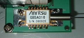
Figure 1
Laser Seed
The
laser seed is biased with a dc current until it
just begins to lase.
An rf
sine wave is
then applied to this laser through a bias tee network.
The internal capacitance and structure of
these small lasers then does something rather amazing.
Instead of slowly turning on and off with the
application of the rf, the diode is driven
far below
threshold during one part of the sine wave and then begins to store
energy on
the opposite swing of the wave. When it
has reached a certain level of stored energy (gain), it “snaps” on and
releases
all of this energy as laser light. The
laser then turns off because all of the gain was extracted. The phenomenon is called “gain-switching”.
Tuning
the seed:
The
balance of rf
and dc power are crucial to get the right pulse.
If dc is too
high, the seed may produce light all the time.
If the rf
is too high, the seed may
produce an “after pulse”.
If either are too
low, the seed won’t produce the desired amplitude
If the seed
temperature is not maintained at a proper setpoint,
the wavelength produced will not match the desired wavelength of the
second
harmonic generator.
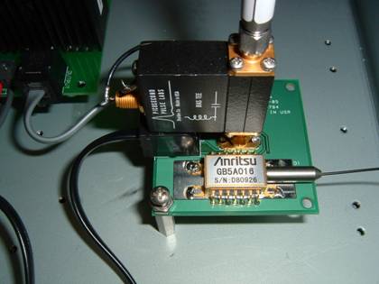
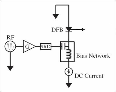
Figure 2 Laser Seed with bias
tee, rf, dc,
and temperature
control inputs
figure 3 Schematic
representation of a gain-switched seed

Figure 4 Optical pulses of
light produced from
a gain-switched seed laser
The
laser seed is light is fiber coupled into a fiber laser amplifer.
The amplifier can take the 1mW average power pulse structure and
amplify it to over 5 Watts. The amplification is very clean and
it would be difficult to discern any differences between the scope
trace of figure 4 and an output pulse trace.
figure 5 A fiber laser amplifer
The
seed and amplifer configuration is what we call "laser Class 1".
This means that the light is totally contained within the apparatus
(fibers) and there are no safety concerns associated with exposure (so
long as the fiber and connections remain intact.) This changes on
the output fiber of the amplifier when the light is launched to free
space.
The fiber launch to free space must occur in a Class 4 Laser
Area. The beam is invisible and quite dangerous if proper
precautions are not taken.
Figure 6 below shows the yellow output fiber entering an optical
assembly on the laser table. This assembly is called the Second
Harmonic Generator (SHG). Its purpose is to take the 1560nm light
from the fiber laser and double its frequency. The resulting
780nm light is useful for driving polarized electrons the CEBAF
accelerator photo-emission gun.
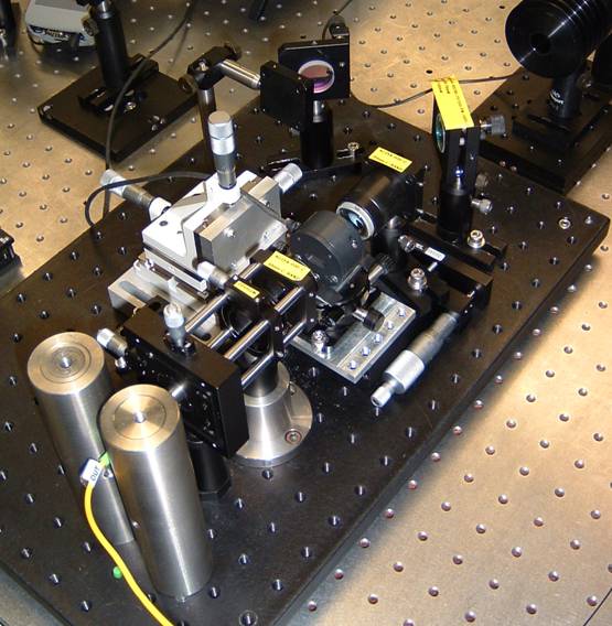
figure 6 A Second Harmonic Generator
Assembly
figure 7 A Schematic representation of the
Second Harmonic Generator Assembly
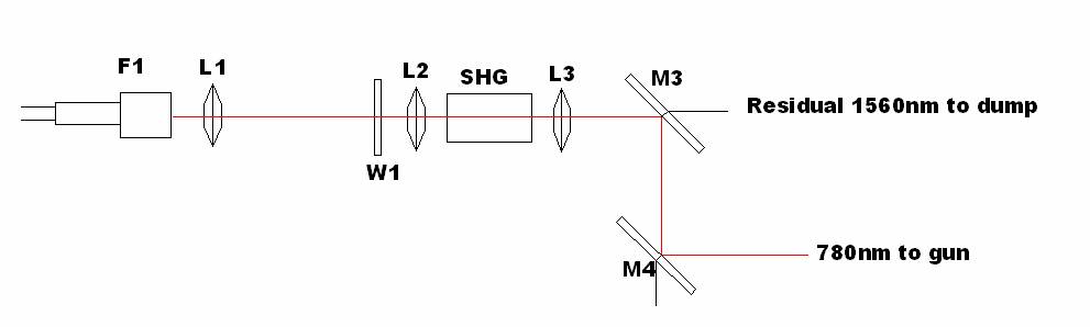
Figure
7 above shows the second harmonic schematic. Light launches from
the fiber laser amplifier output (F1) and is immediately collimated by
lens (L1). The light passes through a 1/2 waveplate (W1) to allow
its linear polarization state to be rotated to match the correct
polarization axis of the doubling crystal. Lens (L2) focuses the
beam to a waist in the SHG crystal. The crystal is made of
periodically polled lithium niobate (PPLN). When properly aligned
and running at the correct temperature, the phase of the crystal is
matched to the phase of the incoming 1560nm light. Harmonic
mixing will then convert some of the 1560nm beam to 780nm
light. Lens (L3) captures the diverging 1560nm and 780nm
light and brings it back to collimation. The combined wavelengths
reach mirror (M3). This is a dichroic mirror that has been coated
to pass the 1560nm light and reflect the 780nm. The 1560nm is
dumped in a safe beamdump, and the 780nm light is reflected off mirror
(M4). The light passes through the other laser table components
and eventually stikes the photo-cathode to produce our electron beam.
As figure 8 demonstrates below, the process of second harmonic
generation is non-linear.
This works to our advantage.
This is ideal for the CEBAF accelerator because only the desired peak pulse will create the 780nm light to drive the electron gun. The small level of DC light between pulses will produce little, if any, 780nm light.
