Readout Controllers
Each front end crate (FASTBUS, VME, or CAMAC) contains a single board computer running a real-time
operating system with networking support (TCP/IP). Currently the only the VxWorks
real-time operating system is supported but there is a project to port the code to linux and other UNIX like operating
systems. (We have also run the software on HP-UX running on an hp7431 PA-RISC single board computer.)
An Ethernet network is generally used for control and monitoring of the embedded controller, downloading calibration
data. Ethernet may also be used for low rate data acquisition (test setup, spying, etc). A higher speed link is
used for the main data flow if rates exceed the ethernet interface speed, (theoretically this is 1MByte/sec but
for all practical purposes is 500 kByte/S). This faste link may take the form of a faster network (FDDI or ATM
in VME), or may be a simple point-to-point data link to another controller such as an FSCC controller in FASTBUS
which transmits data at 40MB/sec to a buffer memory in VME via a parallel data link.
Custom code must be written for each non-network link.
At present (July 1995) CODA is supported for the following bus architectures and hardware configurations.
Here is an index of this page:
VME
- Motorola Several options are availible.
MVME167
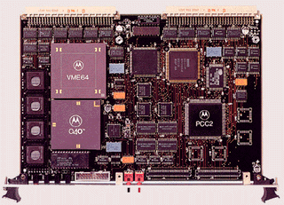 The MVME167 single board VME processor
is based on the 68040 processor and is availible in 25 and 33 MHz clock speeds. The board can be configured with
up to 64Mbytes of memory.
MVME162
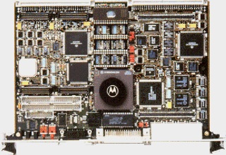 The MVME162 differs from the MVME167
by having a simpler VME interface, only a maximum of 16MB or RAM and an interface to IndustryPack® modules.
MVME1600-1
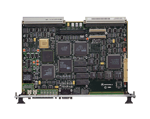 The MVME1600-1 is based on the PowerPCTM 604 processor. It has the advantage of much higher processor speeds and is based internally
on the PCI bus. The board has a single interface for a PMC (PCI bus mezzanine) board which hmay be used to provide
an interface to a high speed network.
- Radstone
PPC603/604
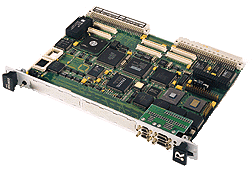 Based on the PowerPCTM603
or 604 processor this board is based internally on the PCI bus and has two PMC interfaces. It may be configured
with up to 128Mbytes of RAM.
CAMAC
- Creative Electronic System - CES 8210 CAMAC Branch
driver in VME with any VME Readout controller (see above). This board has the advantage that all of the CAMAC address
space is mapped into VME address space. CAMAC cycles are initiated by VME memory accesses and are therefore very
fast. This solution requires a type-A crate controller and branch highway cables.
The software library for this module was written at TRIUMF and contributed to CODA.
- Kinetic Systems - KS922 parallel bus crate
controller and KS2917 VMEbus Interface.
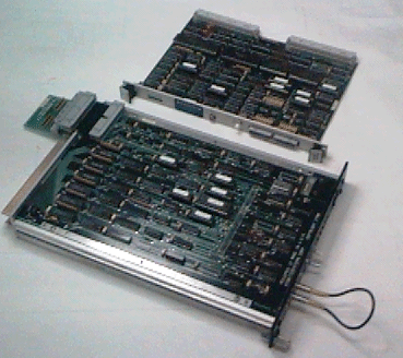
This dual board solution has the disadvantages of costing more than the CES solution if you already own a type-A
controller and is slow. The low speed comes about because the KS2917 VME interface contains a command sequencer
which processes lists of instructions from an onboard memory. Even the simplest CAMAC command requires a list of
instructions to be downloaded and triggeres. This is a fast approach in static readout systems were the list can
be loaded in advance and does not change from one trigger to the next. This is not well suited to the CODA environment.
- Creative Electronic System - VCC2117
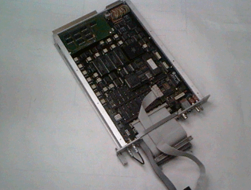
VIC bus to CAMAC interface. The 2117 was designed as an interface between the VIC bus (originally a VME-VME
interconnect) and CAMAC. The board has an onboard 25MHz 68030, up to 16MBytes of RAM and an Ethernet interface.
The Jefferson lab. data acquisition group (i.e. us) ported the VxWorks operating system to this board so that it
could be used as an embedded ROC in CAMAC. The limitations of this system are that data acquisition is limited
to Ethernet speeds and only a single CAMAC crate is supported. With a little work multiple crates could be supported
by making the VCC2117 the controller in an "executive CAMAC crate" which acts as the master to one or
more CAMAC branches. Another alternative would be to modify the ROC code so that the data is transmitted on the
VIC bus. As of this time no interest has been expressed in either option.
notes on CAMAC
The support of CAMAC was critical to the early releases of CODA which were used in detector tests using existing
electronics, mostly CAMAC modules, and low budgets. The philosophy was taken that we should be able to support
as many different CAMAC interfaces as possible. With this in mind CAMAC support in CODA is based on the IEEE standard
"Subroutines for CAMAC" (ANSI/IEEE Std 758-1979) as outlined in "CAMAC instrumentation and
interface standards (ISBN 0-471-89737-X). Any interface conforming to this standard (i.e. following the
IEE library convention with calls like cssa, cdreg, cfsa,cccz etc.) may be used with CODA with minimal modifications
to the code.
FASTBUS
Fastbus is a very popular bus standard in High Energy and Nuclear physics due to the large board area, fast
data transfer rates (40MByte/S) and availability of a wide range of modules tailored to the needs of particle detectors.
Traditionally large scale FASTBUS systems were constructed from many individual crates connected via segment
interconnects (basically an implimentation of the bus on a cable) in some hierachy to one or more mini computers.
The individual controllers in FASTBUS crates were usually lacking in intelligence and contained only a command
sequencer and large buffer memory. The sequencer was triggered by an external event and read all of the data out
of the FASTBUS modules into the buffer memory. the high data rates (40MByte/S) on the backplane lead to a low deadtime
and the buffer memories were read by the mini-computers during the inter-spill gap. This approach was clearly unacceptable
at Jefferson lab since the accelerator has a continuouse wave electron beam with negligable spill structure.
Fortunaltely several commercial "intelligent" FASTBUS controllers now exist which allow us to run
the readout controller software and VxWorks in the FASTBUS crate. All of these controllers have the traditional
buffer memory and high speed FASTBUS sequencer which read the data off the backplane at the high rates required
to reduce deadtime. They also have an embedded microprocessor and associated peripherals which can be used to format
the data and transmit it on a network or over a parallel data link. The distributed "intelligence" allows
data formatting and transport to take place in parallel increasing overall efficiency and reducing dead-time.
In order to use CODA with a controller to conditions must be met. Firstly, a port of VxWorks to the embedded
microprocessor must exist. Secondly, there must be an implementation of the standard library for Fastbus for the
controller.
- Fermilab - FSCC.
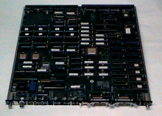 The FSCC is an intelligent FASTBUS crate
controller (Fermilab Smart Crate Controller) used in the DART project
at Fermilab. The board has a high speed FASTBUS sequencer which can optionally pipe data to either a parallel data
link or an internal FIFO memory. The FIFO memory and sequencer can be controlled and read out by a 68020 microprocessor.
The 68020 processor has standard peripherals, memory, ethernet and serial ports which allow it to run the VxWorks
operating system and the CODA readout controller code.
The port of VxWorks to the FSCC was performed by the Jefferson lab data acquisition group and is now supported
by Fermilab.
This board is suitable for small scale data acquisition systems at low data rates. It's main limitations are
the speed of the 68020 processor and the poor performance of the Ethernet interface when used to transfer data
via an Ethernet network. For low event rates with large events this board may be used with a parallel
data link to a VME system in which case it's performance increases dramatically. This is the mechanism used
in hall C. For more information on the FSCC look here.
- Fermilab - FRC.
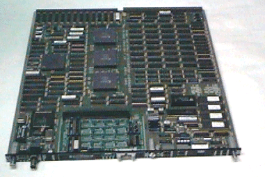 The FRC is the Fermilab successor to the
FSCC. The board has an R3000 series RISC processor with associated peripherals which allow VxWorks to be ported
to the board. This port was performed by the CDF experiment at Fermilab. The FRC had the disadvantage that it was
supported by an experiment rather than a centeral support group. The experiment's priorities were not always a
good match with our own. Also early models of the board, and the VxWorks port had problems which were severe enough
that we did not chose the FRC fr use in hall B. These concerned have since been resolved and the FRC is now well
supported at Fermilab. For more information on the FRC look here.
- Struck - SFI.
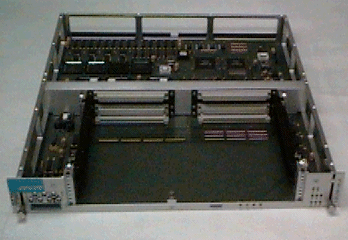 The SFI is a novel approach to a FASTBUS
controller. The problem has always been that while the sequencer logic is more or less standard from one controller
to another the microprocessor and peripherals very quickly become obsolete. Struck's solution to this problem was
to design a FASTBUS controller with the classic sequencer and buffer memory architecture with the controlling microprocessor
replaced by between 1 and 3 VME bus slots. The user can then choose processor and peripherals to match the requirements
of the experiment. For more information on the SFI look here.
At Jefferson lab Hall B will uses the SFI with the Motorola 2300 PowerPC VME card to provide
the processing power required to run data compression and sparsification algorithms. The VME card has two PMC (PCI
bus) slots one of which will be populated with an ATM interface. This will gife the readout controller in FASTBUS
direct access to a high speed network.
Triggering a Readout Controller
Trigger information for the readout controller may come from Trigger Supervisor
(if used) or from other hardware, such as descrete NIM modules. The trigger may be detected either by an interrupt,
or by polling an address (any memory mapped device), or polling a LAM in CAMAC. The CODA
Readout Language has elements for selecting among these possibilities and having multiple trigger sources.
When the ROC detects a trigger it handles the event and calles a user supplied routine (the done routine) which
re-enables the trigger. It is important that the external trigger hardware should lock out new triggers until the
ROC calls the re-enable routine otherwise triggers may be missed. In the cases when the ROC is unable to take a
new trigger the re-enable routine is not called until the condition causing the delay disappears. This is usually
that all the internal buffers are full and the ROC is waiting for the network transmission code to free up buffers.
The Jefferson lab data acquisition group has designed interface hardware for use with the supported readout
controllers. These interfaces include level converters, CAMAC and VME interfaces to the trigger supervisor and
FASTBUS auxillary cards for the SFI and FSCC which provide a high speed parallel data link and trigger supervisor
interface.
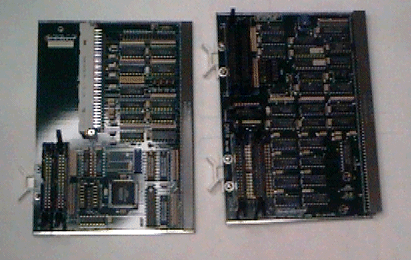 FASTBUS Auxillary interfaces to the trigger
supervisor, FSCC on right SFI on left. The FSCC Interface doubles as data sources for a 40 MByte/Sec parallel data
link. The large grey connector on the SFI interface caries the outer two rows of pins from the VME P2 conector
of the slot containing the VME processor.
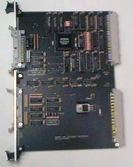 VME interface to the trigger supervisor.
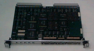
High speed (40 MByte/Sec parallel data link, VME end.
For more detail see: Readout controller user guide
Harsh Reality
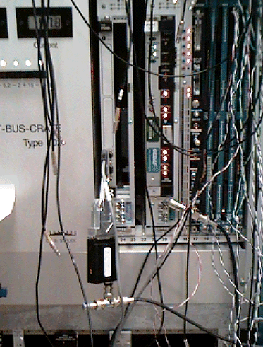 Just in case you think this is all
clean and easy here is a picture of a real Readout controller in a test setup in our lab.
 The MVME167 single board VME processor
is based on the 68040 processor and is availible in 25 and 33 MHz clock speeds. The board can be configured with
up to 64Mbytes of memory.
  The MVME162 differs from the MVME167
by having a simpler VME interface, only a maximum of 16MB or RAM and an interface to IndustryPack® modules.
 The MVME1600-1 is based on the PowerPCTM 604 processor. It has the advantage of much higher processor speeds and is based internally
on the PCI bus. The board has a single interface for a PMC (PCI bus mezzanine) board which hmay be used to provide
an interface to a high speed network.
The MVME1600-1 is based on the PowerPCTM 604 processor. It has the advantage of much higher processor speeds and is based internally
on the PCI bus. The board has a single interface for a PMC (PCI bus mezzanine) board which hmay be used to provide
an interface to a high speed network.Based on the PowerPCTM603
or 604 processor this board is based internally on the PCI bus and has two PMC interfaces. It may be configured
with up to 128Mbytes of RAM.


 The FSCC is an intelligent FASTBUS crate
controller (Fermilab Smart Crate Controller) used in the
  The FRC is the Fermilab successor to the
FSCC. The board has an R3000 series RISC processor with associated peripherals which allow VxWorks to be ported
to the board. This port was performed by the CDF experiment at Fermilab. The FRC had the disadvantage that it was
supported by an experiment rather than a centeral support group. The experiment's priorities were not always a
good match with our own. Also early models of the board, and the VxWorks port had problems which were severe enough
that we did not chose the FRC fr use in hall B. These concerned have since been resolved and the FRC is now well
supported at Fermilab. For more information on the FRC look
  The SFI is a novel approach to a FASTBUS
controller. The problem has always been that while the sequencer logic is more or less standard from one controller
to another the microprocessor and peripherals very quickly become obsolete. Struck's solution to this problem was
to design a FASTBUS controller with the classic sequencer and buffer memory architecture with the controlling microprocessor
replaced by between 1 and 3 VME bus slots. The user can then choose processor and peripherals to match the requirements
of the experiment. For more information on the SFI look
  FASTBUS Auxillary interfaces to the trigger
supervisor, FSCC on right SFI on left. The FSCC Interface doubles as data sources for a 40 MByte/Sec parallel data
link. The large grey connector on the SFI interface caries the outer two rows of pins from the VME P2 conector
of the slot containing the VME processor.
 VME interface to the trigger supervisor.

 Just in case you think this is all
clean and easy here is a picture of a real Readout controller in a test setup in our lab.