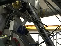
1 SVT side view |
 2 SVT side view |
 3 SVT on rotation fixture. |
 4 SVT module with HFCB |
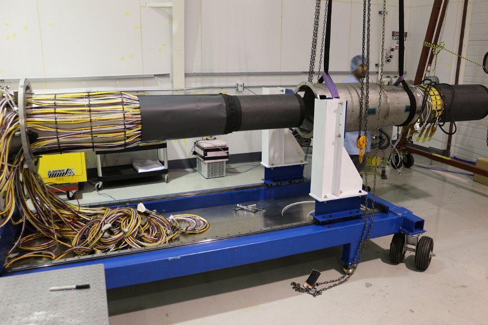
 5 SVT lifted to be placed on transportation cart |
 6 SVT lifted to be placed on transportation cart |
 7 SVT lifted to be placed on transportation cart |
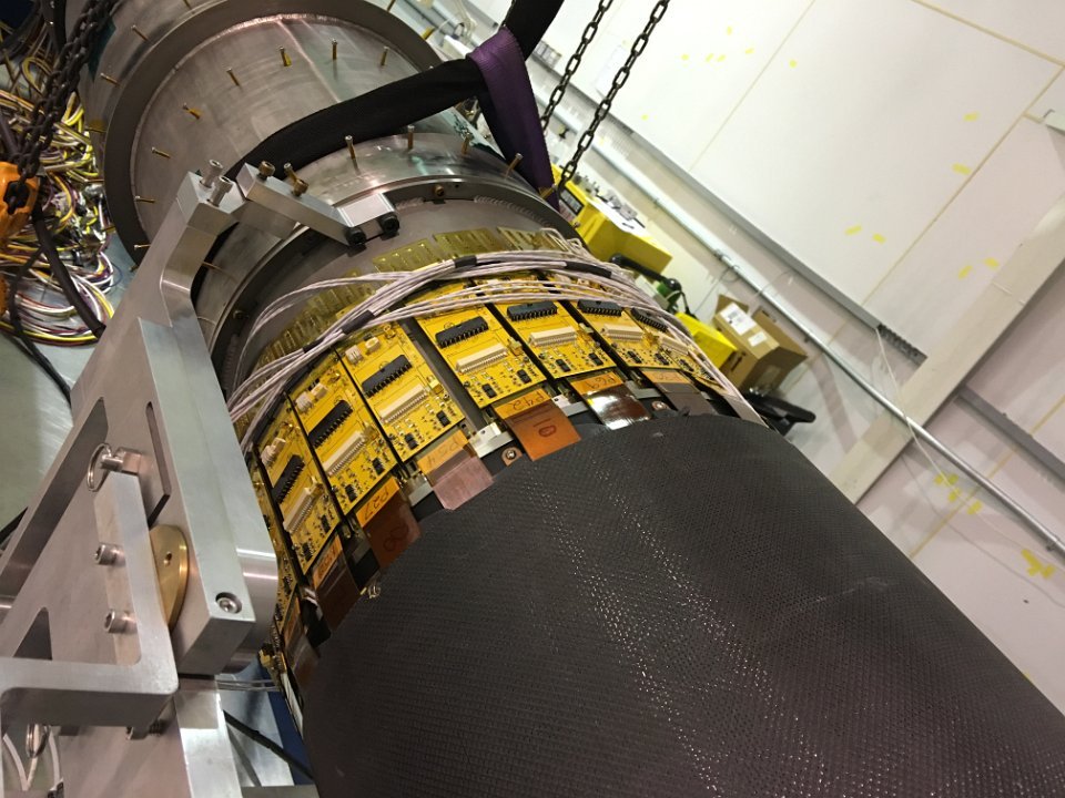 8 SVT level 1 readout electronics |
 9 SVT isometric view |
 10 SVT in vertical position without outer cover |
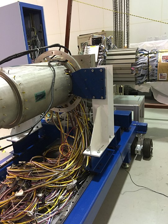
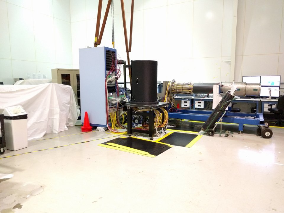
 11 SVT in transportation cart |
 12 SVT hybrid flex circuit board (HFCB) cables |
 13 SVT HFCBs |
 14 SVT HFCBs |
 15 SVT front view |
 16 SVT cables. |
 17 SVT assembled modules |
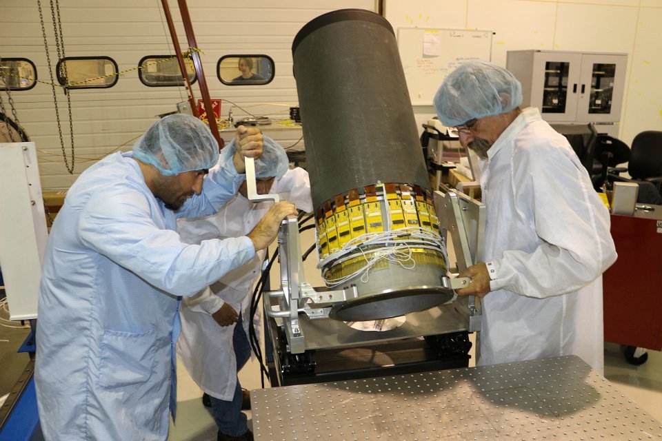
 18 Steve Christo assembling SVT on insertion track |
 19 Saptarshi Mandal supervising mounting of SVT on insertion track |
 20 Rotation of SVT to vertical position |
 21 Rotation of SVT to vertical position |
 22 Rotation of SVT to vertical position |
 23 Rotation of SVT to vertical position |
 24 Rotation of SVT to vertical position |
 25 Rotation of SVT to vertical position |
 26 Rotation of SVT to vertical position |
 27 Rotation of SVT to vertical position |
 28 Replacing repaired module in R4 |
 29 Replacing repaired module in R4 |
 30 Replacing carbon fiber cover |
 31 R4 in vertical position - cabling completed |
 32 R4 in vertical position - cable bundles separated by type |
 33 Preparation to mount SVT on insertion track |
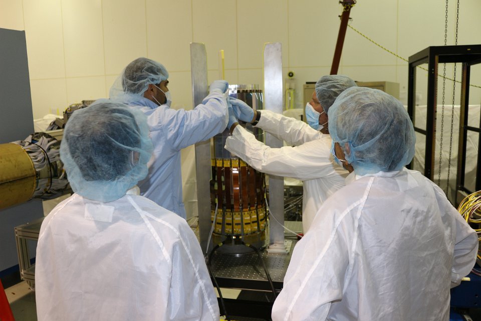
 34 Module extraction from R4 |
 35 Module extraction from R4 |
 36 Module extraction from R4 |
 37 Module extraction from R4 |
 38 Module extraction from R4 |
 39 Insertion track flange |
 40 Extracted module |
 41 Extracted module closeup |
 42 Control system monitors |
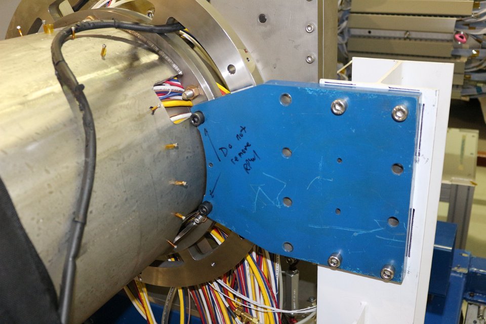
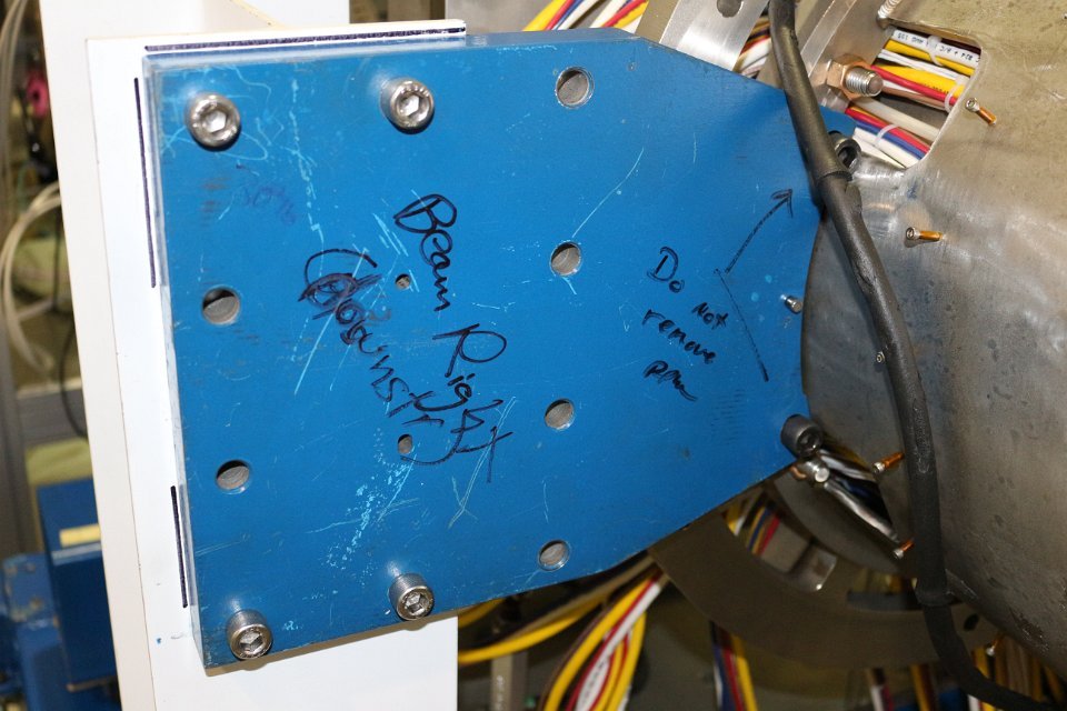 43 Close up of insertion track flange |
 44 Close up of HFCB module |
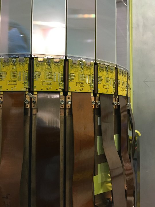 45 Close up of HFCB cables |