|
|
TITLE: |
||
|
|
|||
|
DOCUMENT ID: |
6151 Appendix T1 Pressure
System Project Implementation and Documentation Requirements |
||
|
|
|||
|
NOTICE: |
This
document is currently under review.
All requirements outlined within this document apply to current
laboratory operations until new content is approved, released, and published. |
||
1.0 Purpose
This technical appendix provides
requirement for specific project implementation and documentation of pressure
system design, fabrication, testing, inspection maintenance, repair and
operation at Jefferson Lab.
2.0 Scope
The scope of this technical appendix covers any new construction of a pressure system or maintenance, repair, or modification of an existing pressure system. A pressure system shall be defined as in ES&H Manual Chapter 6151 Pressure Systems. At any point in the process, the Pressure Systems Committee shall be available for direction in applying this appendix.
New construction consists of producing either original systems or copies of existing designs. Repair consists of restoring the pressure system to its original design condition. Modification consists of a change in service of a pressure system or the expansion of the capability of a pressure system, e.g. extending its capabilities by increasing the nominal operating pressure. Changing the service also includes any change in the application or change in the location of the vessel or piping if the structural support is affected.
The full rigor of the requirements for project implementation and documentation provided here address new pressure system design and construction. In the case of repairs or modifications to pressure systems, the Design Authority is responsible for:
· Directing the repair or modification in accordance with the original construction codes of the pressure system. If no code is applicable, the Design Authority shall use the original design documentation for the basis of the changes; if none exists, sound engineering principles shall be used.
· Coordinating with the Facilities Management and Logistics Department for any repairs and associated documentation to stamped pressure vessels.
· Issuing specific Standard Operating Procedures (SOPs) as required to direct low hazard repairs.
· Storing documentation for all repairs or modifications within DocuShare in appropriate Folders for the pressure system including information such as any necessary calculations verifying the design and hazard class, documentation identifying the material or component, drawing (for Class A welds), photo or sketch, and pressure testing SOP, if required.
This appendix recognizes that the work product required for a given pressure system is based upon the complexity of the new design or modification. For pressure system projects with reduced complexity, i.e. commercially available tanks; the Design Authority is responsible for making appropriate notes in the Project Folder when components of this appendix and/or the Pressure System Checklist are not relevant.
Pressure system projects with a Risk Code of 0 or 1 as defined by ES&H Manual Chapter 3210 Work Planning, Control, and Authorization Process; containing a fluid that is nonflammable, nontoxic and not damaging to human tissues; and with a calculated stored energy less than 100 kJ or 0.0476 lb TNT are considered low hazard.[1] These low hazard projects require, at a minimum, any necessary calculations verifying the design and hazard class, documentation identifying the material or component, drawing (for Class A welds), photo or sketch, and pressure testing SOP to be filed in DocuShare under a pressure system identification number. The SOP Pressure Test Worksheet may serve as the final inspection report for these low hazard projects.
3.0 Responsibilities
3.1 Design Authority is responsible for creating and maintaining the Pressure System Project Folder within DocuShare until close out of the project. Additional responsibilities are described in Section 4 of this Appendix.
3.2 Document Control Group shall provide assistance to the Design Authority when inputting the various forms of information in the DocuShare System.
3.3 Quality Assurance Personnel shall verify that documentation of the pressure system is complete before operation of a pressure system. Quality Assurance Personnel shall maintain the Welding/Brazing Directory within DocuShare.
3.4 Pressure Systems Committee provides guidance to Design Authorities on pressure systems matters and supports Peer Reviews for pressure systems as required.
3.5 Pressure Systems Committee Designee provides pressure system identification numbers, assists in setting up DocuShare folders, inputting project documentation and coordinates active pressure system inspection reminders. Current contact information for the Pressure System Committee Designee shall be provided in the Pressure Systems Directory within DocuShare.
4.0 Process Steps and Expectations
4.1 The Design Authority shall determine whether a proposed design fits the definition of pressure system provided in ES&H Manual Chapter 6151 Pressure Systems. If required, contact the Pressure Systems Committee for assistance in application of this definition. A link to the current membership list is provided in the Pressure Systems Directory of DocuShare.
4.2 For a new pressure system, the Design Authority shall consult with the Pressure Systems Committee Designee to create a unique identification number within the Pressure Systems Directory of DocuShare for a pressure system project when a new design is identified as a pressure system. The Design Authority shall create a corresponding title for the pressure system which includes clear terms describing the system and its location, if relevant. The pressure system identification number shall follow the format below:
The pressure system identification number shall follow the format below:
PS-XXX-YY-NNN
For consistency and traceability, the Design Authority shall use this pressure system identification number on all documentation to be included in the Project Folder.
4.3 The Design Authority shall create a Project Folder within DocuShare. The Pressure Systems Committee Designee shall provide assistance as required. The Design Authority shall grant write privileges to Jefferson Lab personnel involved that receive, generate, or distribute documents for a specific pressure system.
This Project Folder shall follow the template included in the Engineering – Pressure Systems Directory – Pressure System Template Folder in DocuShare. A copy of the template is provided in Figure 1. The Project Folder shall contain the sub-folders listed below.
Figure 1. Directory of Sample Pressure Systems as
viewed in DocuShare
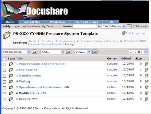
A Pressure System Checklist (provided at the end of this appendix) within the Project Status and Information Folder shall be initiated and maintained by the Design Authority for all pressure system projects not identified as low hazard projects as defined in Section 2.0 - Scope of this Appendix. The Pressure System Checklist serves as a prompt for the Design Authority as well as an auditing tool for the Quality Assurance representative. “Complete” status on the checklist shall be given when that portion of the work process is documented and filed within DocuShare.
4.3.1 Project Status and Information Folder – includes the Pressure System Checklist and documentation by the Quality Assurance representative of the pressure system’s acceptability for use. Project status reports and schedules may be included here to assist in project and inspection coordination.
4.3.2 Engineering Folder – includes engineering related information such as:
· applicable ASME Codes for all components of the pressure system both directly applicable or using equivalent measures, documentation of Peer Review of decision to use equivalent measures.
· engineering calculations signed-off by Technical Review which may include details of the service description, design conditions (loading), philosophy of design (sections of the ASME codes used and methods for evaluating other loads) and philosophy of construction (materials and material compatibility), methods of support, and the actual analysis and results.
· information on process flow, pressure drop, heat transfer or other characteristics which would be utilized to demonstrate the system’s capability to operate under the service conditions and demonstrate system safety aspects.
· resulting signed-off drawings and/or sketches with Bill of Materials, detailed weld requirements (material specifications, type of joint, preheat and past treat requirements, etc.), and identification requirements.
· documentation of Peer Reviews of Non-Code Qualified Design Elements
· design review documentation specific to the pressure system.
4.3.3 Manufacturing Folder – includes Subfolders for the following information:
·
Purchasing
includes copies of or links to Purchase Orders and any other pertinent
details associated with the Purchase Order.
· Statement of Work/Fabrication Plan/Bill of Materials including scope, reference documents and specifications, technical requirements, quality assurance and quality control requirements.
·
Material
Certifications includes material test reports and/or certificates of
conformance to demonstrate material conformance to code and material
compatibility for process system service.
Material traceability may be documented on an as-built drawing by
purchase order number or other designator to track where an item was installed
into the system.
· Receipt Inspection includes documentation of the as received condition.
·
Fabrication
includes travelers and other in-process work documents as required.
·
Welding/Brazing
for in-house fabrication includes information
specific to the pressure
system fabrication such as welding and brazing traceability documentation.
This folder shall provide a link to the Welding/Brazing Directory in DocuShare
which stores information on Welding Performance Qualifications, Procedure
Qualification Records, Welding Procedure Specifications, Visual Examination
Procedures and other general welding/brazing information.
·
Welding/Brazing
for outside procurement includes vendor information on welds/brazes
performed including welder/brazer and process information as well as results
from the weld/braze inspection process.
·
Certifications
includes information specific to the pressure
system or a link to the Welding/Brazing Directory where required.
·
Examinations
and Inspections includes examination and inspection documents specific to
the pressure
system. Vendor component pressure
testing shall be stored within this folder.
4.3.4 Testing Folder – includes testing procedures such as Temporary Operational Safety Procedures (TOSPs), Standard Operating Procedures (SOPs), or other applicable test procedures for final leak/pressure tests, test equipment calibration and certification documents, leak/pressure tests and sign off for components that are ready for installation or use.
4.3.5 Operation, Maintenance and In-service Inspection – includes safety related operational and maintenance procedures. Includes results of inspections after initial operation as well as intervals for those inspections.
4.3.6 Modifications Folder – (Modifications shall be separated by Sub-Folder) includes work product for modifications to pressure systems. For complex modifications, work would involve all the steps included for new pressure system design and, consequently, the Design Authority shall use Project Status, Engineering, Manufacturing, and Testing Sub-Folders within the associated Modifications Sub-Folder. For simple modifications, a single folder is likely to suffice for the storage of design criteria and calculations; sketches, photographs and/or drawings as appropriate; fabrication documentation; and pressure testing procedures and results.
4.3.7 Repairs Folder - includes information such as any necessary calculations verifying the design and hazard class, documentation identifying the material or component, photo or sketch, and pressure testing SOP, if required.
4.4 The
Design Authority shall define the applicable ASME Codes for all components of
the pressure system whether those codes apply directly or indirectly through
equivalent measures. ES&H Manual Chapter
6151 Appendix T2 Pressure Systems Design Program provides guidance in the applicability of the ASME Codes. The
Design Authority shall conduct a Peer Review of the Code applicability if
equivalent measures will be employed.
A component listing of the applicable ASME codes, and, if required, equivalency
measures and the associated Peer Review sign-off shall be documented and stored
within the Engineering Folder.
4.5 The
Design Authority shall define project specific design criteria. The overall design is governed by the system
requirements as defined by an outside customer or internally by Jefferson Lab. These requirements set the stage for such
parameters as the system working pressure, the operating temperature, the
possibility of cyclic loading, any cleanliness requirements, specific material
properties and welding requirements. Design criteria
shall be documented and stored within the Engineering Folder.
4.6 The Design Authority shall perform the design phase of the pressure system including Technical Reviews of calculations, specifications and drawings and Peer Reviews of Non-Code Qualified Construction Elements. ES&H Manual Chapter 6151 Appendix T2 Pressure Systems Design Program provides guidance for the design process and application of ASME codes. Work product from the design phase such as engineering calculations, design specifications, system requirements, and resulting drawings shall be documented in the Engineering Folder of DocuShare.
If the design of the pressure system is completed by a subcontractor, the subcontractor must comply with the requirements of the applicable ASME codes identified by the Design Authority. If equivalent measures are employed, an independent Peer Review within the subcontractor’s organization including the Design Authority or a designee must be performed for all Non-Code Qualified Design Elements.
4.7 Using sound engineering principles, the Design Authority shall determine whether a final design review of the pressure system is required and shall conduct that review prior to releasing final drawings for fabrication Additional design reviews may be required depending on the complexity of the project. Records of the results of the reviews shall be maintained in the Engineering Folder. Design reviews shall include another qualified Design Authority not involved with the project and, as required, representatives of groups concerned or involved with the respective design such as Quality Assurance, Procurement, and various subject matter experts knowledgeable with the Jefferson Lab specific application of the pressure system. The Pressure Systems Committee maintains a referral list of pressure systems Design Authorities for use as subject matter experts. Examples of subjects to be addressed in the design review include:
· Purpose of design and background on project.
· Review of the design requirements and design criteria.
· Review of design input and design outputs.
· Design approach and methodology: applicable codes and standards used; modeling and analysis tools and results; sketches or preliminary drawings; preliminary results of hazards analysis; fabrication process; results of any trade studies.
· Review status of design verification and validations.
· Scope changes that affect the project.
4.8 Upon completion of the final design review or after determining that a final design review is not warranted, the Design Authority shall finalize the fabrication strategy: in-house fabrication or outside procurement. The make/buy decision shall be noted on the Pressure System Checklist in the Project Status and Information Folder. For outside procurement, the Design Authority shall follow Step 4.9. For in-house fabrication, the Design Authority shall follow Step 4.10. Steps 4.11 through 4.14 are required for both in-house fabrication and outside procurement. For pressure systems to be built on-site by subcontractors, the Design Authority is responsible for completing a Statement of Work (4.9.1), following the Jefferson Lab procurement process (4.9.2), ensuring that the system is pressure tested according to the applicable ASME Codes (4.11), and following steps 4.12, 4.13 and 4.14 for operation and maintenance guidelines, final safety walk-through and project close-out.
Note: Jefferson Lab does not have certification to stamp ASME vessels. Pressure vessels where ASME codes can be directly applied must be procured from a company authorized to use the ASME “U” or “UM” stamp. Pressure vessels that cannot be stamped because of pressure range, vessel geometry, special materials, etc. that have not been considered by the ASME codes can be fabricated at Jefferson Lab or procured outside provided an equivalent or higher level of protection as afforded by the ASME codes is implemented.
4.9 Procuring an Outside Fabricated Pressure System:
4.9.1 Unless the pressure system is a well-defined standard product such as a small air compressor receiving tank and piping, the Design Authority shall complete a Statement of Work (SOW) at the start of the procurement process. The SOW shall address the unique requirements of the pressure system. Where the pressure system is a part of a procurement of a larger system, the Design Authority shall ensure that the unique requirements for that pressure system are included within the larger procurement technical specification. The Design Authority is encouraged to include a final inspection by Jefferson Lab personnel before shipping to Jefferson Lab.
The SOW shall be reviewed and signed off by another Design Authority and approved by the Group Supervisor. A copy of the completed SOW shall be stored in the appropriate folder within DocuShare.
4.9.2 The Design Authority or appropriate designee (for the procurement process, the responsible party is identified as the Subcontracting Officer’s Technical Representative (SOTR) shall follow the established Jefferson Lab procurement process and maintain all documentation in the Manufacturing Folder as listed in Step 4.3.
With direction from the Design Authority or SOTR and provided that write privileges have been allowed, procurement personnel (Subcontracting Officer) may input documentation directly into the appropriate folder in DocuShare.
4.9.3 The SOTR with the assistance of Quality Assurance Personnel shall work with the manufacturer to ensure ASME codes or their equivalent (verified by Peer Review of Non-Code Qualified Construction Elements) are implemented throughout the design, fabrication and any initial pressure testing.
4.9.4 The SOTR with the assistance of Quality Assurance Personnel shall coordinate the receipt inspection which shall include, at a minimum, visual and dimensional inspection and verification of documentation. Work product from this receipt inspection shall be stored in the appropriate folder. For code-stamped pressure vessels, the Manufacturer Data Report, signed by the manufacturer’s representative and the National Board commissioned inspector shall be stored in the Material Certification Sub-Folder with a copy forwarded to the Facilities Management Department or, alternatively, notice made that the document is in DocuShare.
4.9.5 The Design Authority shall release the pressure system component(s) to the appropriate service groups for installation. Appropriate component identification and documentation shall remain with the pressure system throughout the installation process.
4.10
Fabricating
a Pressure
System In-house
4.10.1 The Design Authority shall develop and maintain a Fabrication Plan for pressure systems to be made in-house. Documented Peer Review approval is required where ASME code fabrication requirements cannot be directly applied. The Fabrication Plan shall be coordinated with all service groups affected such as Procurement, Quality Assurance/Continuous Improvement (QA/CI), Machine Shop, and others as applicable. The Fabrication Plan shall cover purchasing requirements, QA/CI requirements, schedule, fabrication resource requirements and travelers. The Design Authority shall use standard travelers wherever possible and develop new travelers when required. Part and material identification requirements shall be included on the traveler. The Fabrication Plan shall be stored in the appropriate folder within DocuShare.
4.10.2 The Design Authority shall follow the established Jefferson Lab procurement process for parts and materials listed in the Bill of Materials. All parts and materials shall be identified as being part of a pressure system to facilitate material control upon receipt. Work product from the procurement process shall be stored in the appropriate folder in DocuShare.
4.10.3 The Design Authority shall coordinate receipt inspection of all pressure system parts and materials. Receipt inspection shall include, at a minimum, visual and dimensional inspection and verification of documentation.
4.10.4 Following the schedule outlined in the Fabrication Plan, the Design Authority shall release parts and materials to the appropriate service groups for fabrication. Appropriate material identification and documentation shall remain with the parts and materials throughout the fabrication process.
4.10.5 At any point in the process where changes to drawings or specifications are required, the responsible party (Design Authority, Quality Assurance representative, etc.) shall initiate an Engineering Change Order (ECO), follow established ECO policy, and document all changes and as-builts in the Manufacturing Folder of DocuShare. Documented Peer Review approval is required where ASME code design or fabrication requirements cannot be directly applied.
4.10.6 Any welding or brazing that is performed during the fabrication process shall follow ES&H Manual Chapter 6122 Hot Work (i.e. Welding, Cutting, Brazing, and Grinding) Safety Program and ES&H Manual Welding and Brazing Program Supplement. Weld/braze procedures and qualifications, material, inspection and examination requirements are included in these references for welded and brazed joints.
4.11
Installing
and Testing a Pressure System – ES&H Manual Chapter
6151 Appendix T4 Pressure Systems Pressure Testing Program provides an
outline for leak tests and pressure testing.
The Design
Authority shall coordinate leak tests and pressure tests at the component
stage of fabrication or after final system installation as required by
appropriate ASME codes. For piping
systems, the testing requirements are described in ASME B31.3. Pressure vessel testing requirements are
described in ASME BPV Code Section VIII.
Work product from leak and pressure tests shall be documented in the
Testing Folder within DocuShare.
4.12 The Design Authority shall outline safety related operational and maintenance procedures for the pressure system and shall file these in the Operation, Maintenance and In-service Inspection Folder. The Design Authority shall identify the in-service inspection interval and furnish that information to the Pressure Systems Committee Designee for input into a notification system within DocuShare and the Operation, Maintenance and In-service Inspection Folder.
4.13 Final Safety Walk-Through - The Quality Assurance representative shall perform the final safety walk-through for the pressure system before it can be released for operation. This effort shall include reviewing the Pressure System Checklist and DocuShare Folder for completeness, and ensuring that pressure system marking is consistent with applicable code requirements. Required nameplate information for pressure vessels is outlined in ES&H Manual Chapter 6151 Appendix T2 Pressure Systems Design Program. The Quality Assurance representative shall issue a final inspection report stating the pressure system’s acceptability for use and shall document such in the Project Status folder.
4.14 After a new pressure system has been approved for use, the Design Authority closes out the project by making all folders except the Operation, Maintenance, and In-Service Inspection; Modifications; and Repair Folders “Read Only.” For modifications and repairs, the Design Authority closes out the project by making the associated Modifications or Repairs Sub-Folder “Read Only.”
5.0 References
ES&H Manual Chapter 6122 Hot Work (i.e. Welding, Cutting, Brazing, and Grinding) Safety Program
ES&H Manual Welding and Brazing Program Supplement
JSA, LLC Acquisition Policy Manual
American Society of Mechanical Engineers (ASME) Boiler and Pressure Vessel (BPV)
Code, Section VIII: Rules for Construction
of Pressure Vessels, Divisions I & II
ASME Code for Pressure Piping B31, B31.3 Process Piping
6.0
Worksheet 
Pressure System Checklist
|
|
|
||
|
|
Engineering / Design Information Folder includes |
Completion Date* |
|
|
- Design Criteria and
Applicable Codes |
|
||
|
- Design Calculations signed
off by Technical Review |
|
||
|
- Peer Review of Non-Code
Qualified Design Elements |
|
||
|
- Drawings or sketches
marked as a pressure system and Signed Off |
|
||
|
- Design Reviews |
|
||
|
|
|||
|
|
|
||
|
|
Manufacturing Folder includes or is linked to: |
Completion Date |
|
|
|
|||
|
- Statement of Work or
Fabrication Plan |
|
||
|
- Orders for all materials
per BOM placed |
|
||
|
- Receipt of certifications
for materials (MDR for stamped vessels) |
|
||
|
- Inspections for all parts
/ subassemblies received |
|
||
|
- Fabrication Documentation |
|
||
|
- Welding Documentation |
|
||
|
- Examination/Inspection
Documentation |
|
||
|
|
|||
|
|
|||
|
|
Testing Folder includes |
Completion Date |
|
|
- TOSP / SOP ready for use |
|
||
|
- Final Leak Test / Pressure
Test |
|
||
|
|
|
||
|
|
|
|
|
|
Operation and Maintenance |
Completion Date |
||
|
- Safety related operation and maintenance outline |
|
||
|
|
|||
|
|
|
|
|
|
Project Status and Information Folder
includes: |
Completion Date |
||
|
-
Final QA inspection report that pressure system is ready for use |
|
||
|
|
|
||
|
|
|
|
|
Notes: |
||
|
|
||
|
|
||
|
* Completion Date is the date
the documentation is filed in the appropriate DocuShare folder. If an item on the Checklist is not
applicable, the design authority shall mark “NA”. |
||
7.0 Revision Summary
Revision 3.2 – 05/17/13 – Added notice to reflect current lab operations.
Revision 3.1 – 04/14/11 – Updated links to ES&H Manual Chapter 6122 and Welding and Brazing Supplement.
![]()
![]()
![]()
![]()
|
ISSUING
AUTHORITY |
TECHNICAL
POINT-OF-CONTACT |
APPROVAL
DATE |
REVIEW
REQUIRED DATE |
REV. |
Page 1 of 18 |
|
ESH&Q Division |
12/07/09 |
12/07/12 |
3.2 |