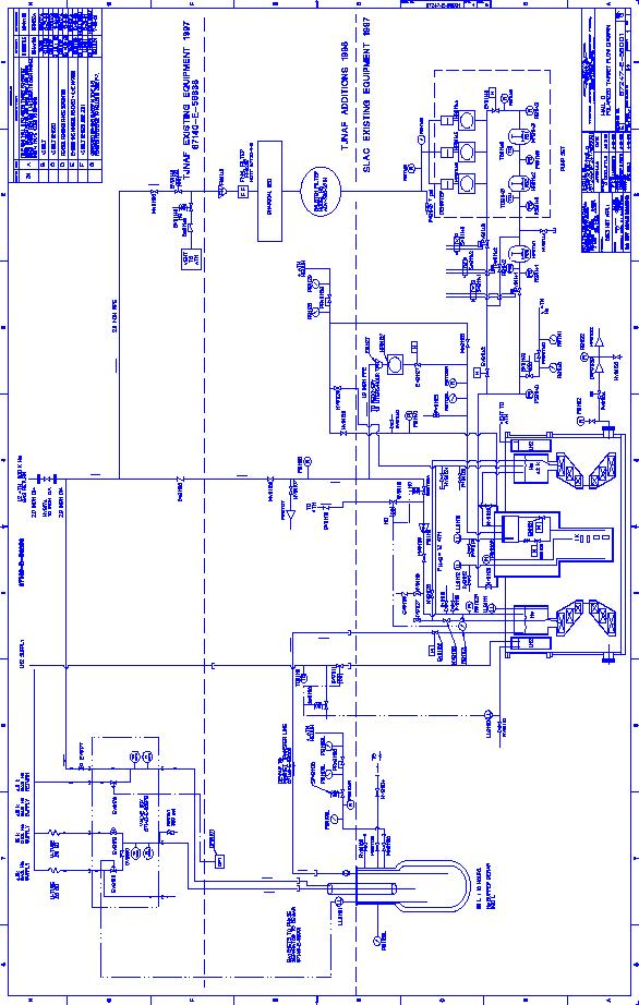
The official Hall C flow diagram for the polarized target is shown in Fig. 2. The basic design and operation of the cryogenic system is summarized below.
Cold helium vapor (5K, 2.5 bar) is supplied to Hall C by the End Station Refrigerator Facility (ESR). This vapor is condensed into liquid by expansion through Joule-Thompson (JT) valve EV9180 and collected in a commercial 500 l LHe dewar (the ``buffer'' dewar). Boil-off from this dewar is returned to ESR as 5.5 K, 1.2 bar vapor through EV9178 (i.e. ``Cold Return''). This valve is kept partially closed in order to build up a pressure of about 1.4 bar inside the buffer dewar. This pressure is used to force LHe from the buffer dewar to the target cryostat. The option of returning the buffer dewar boil-off to ESR's warm return line exists via EV9177, but should be exercised only during the initial cooling of the buffer dewar. Two PID1 control loops are used to maintain both a constant liquid level and gas pressure in the buffer dewar, as described below. Operation of the PID controls is discussed in Section 6.
Liquid helium from the buffer dewar is supplied to the superconducting magnet through a 2 m long, vacuum-insulated transfer hose. Replenishment of the magnet's liquid helium level, as well as the liquid nitrogen heat shield, is performed periodically by two fully automated sequences described in Sections 7.2 and 7.1.
Liquid helium from the magnet dewar is continuously siphoned into the 1 K refrigerator. The liquid first enters a stainless steel ``separator'' pot where the vapor is removed from the boiling liquid by a metal bellows pump on the main gas panel. LHe from the separator drains through a 5 mm copper tube into the 1 K refrigerator's evaporation chamber where the vapor pressure is reduced to less than 1 mbar by a system of Roots and rotary-vane vacuum pumps. The copper tube is heat sunk to a series of ten perforated copper plates that act as liquid-gas heat exchangers between the incoming liquid and the outgoing vapor. The flow of liquid through the heat exchangers is metered by needle valve EV91120 (aka the ``Run'' valve). A PID loop controls the Run valve to maintain a constant level of LHe in the evaporation chamber, or ``tailpiece''. A second needle valve, EV91121 can be used to bypass the heat exchangers. The bypass valve is usually kept closed.
All the cryogenic subsystems are monitored by a variety of flow and pressure transducers, liquid level meters, and cryogenic thermometers. The various components of the system are described in further detail in the ensuing sections. A list of the control hardware is presented in Sec. 9.