Two pieces of electronics are necessary to make the stepper motor work, a control circuit and a driver circuit. The IP-Stepper is an industry pack mounted on the VME carrier board and is used as the controller for two valves. Thus there are two IP-Steppers on the carrier board. The controller sends two signals to the drive circuit: a series of TTL pulses at a specified frequency, and a TTL-compatible direction bit. The drive circuit amplifies and redirects the TTL pulses in a specific order to the six windings of the stepper motor. Based on the direction bit, the order will cause the motor to rotate in a clockwise or counterclockwise fashion. The drive circuit is designed by the Target Group and is located in a separate enclosure from the controller. The driver also allows for manual control of the stepper motor using a pair of panel mounted switches and an internal 60 Hz pulser.
The four stepper motor valves each has a rotary optical encoder mounted either to the motor shaft or to the valve stem itself. The encoder is read by a display unit (US Digital ED2), and has a resolution of 0.0025 revolutions. The motors themselves only have a resolution of 0.005 revolutions. The ED2 units (there are two of them) are read into the control computer over serial lines.
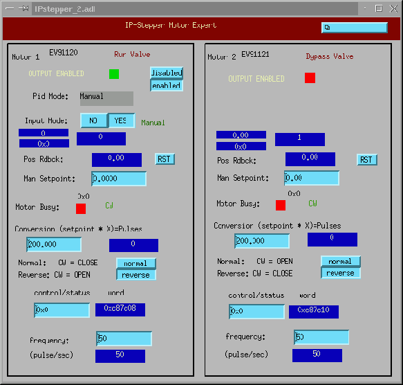
For the most part the valves can be operated without any knowledge that a stepper motor is used to drive the valve. However, an ``expert'' GUI exists for the valves that can be used to modify the stepper control parameters. Figure 11 show one such screen, for the Run and Bypass valves. A similar GUI is available for the other two valves. Both are accessible from the ``Instrument Expert Controls'' menu at the top of the Expert GUI.
The following table describes most of this GUI's features.