Instructions for Low Field Setting of HRS Magnets (8/9/06) updated 1/7/08
These instructions exist because the NMR gaussmeters (D-N on the tools screen) will not work below about 450 MeV/c and at very low momentum settings using the field is more reliable than the current in the quadrupoles. So at low momentum settings, < 450 MeV/c the Hall Probe magnetic field (D-G for the dipole on the tools screen) is used. The Hall Probe field for the quads is used as well.
Do everything as normal except as noted below for
the momentum ranges specified. In fact the controls have been updated so
that even at low momenta doing everything as normal should work. What follows
is a description of the underlying principles and parameters used in the low
momentum setting regime.
For normal spectrometer parameters see hrs_controls_parameters.htm
n.b. When setting a quad by field, cycling is not necessary. Otherwise, cycle the quads, especially for low settings. (see HRS_Magnet_Cycling.doc )
Precision:
As a rule the quads should be set to better than 10-3 and the dipole to better than 10-4.
The simplest prescription for the dipoles is to say don’t tweak the current in increments less than 0.1 Amps.
Similarly, for the quads keep the tweaking at >0.5 Amps.
Magnets in general:
Unfortunately, our controls are not perfect. In most cases the input “set current” is not exactly what you get back as the final achieved current. The good news is the offsets are generally pretty constant. The user should keep these offsets in mind if trying to reach a particular target current. Also, these are large magnets with a lot of stored energy. Nothing changes quickly. Be patient! Starting a strip chart showing the magnet currents and fields may be helpful in determining whether or not the current and or field are really changing and will give a good indication of the practical level of precision one can achieve. In order to set the right dipole quickly, at least relatively speaking, requires special attention. This is described in more detail below.
There is an ongoing problem that sometimes the controls readback of the Hall probes freezes. This is fixed by rebooting the IOC for whichever arm is giving the problem. If something looks funny check that the field readback is working (you should see some variation in the last digit of the readback). If necessary reboot.
n.b. The Hall Probes and NMR probes are, and have
always been, different devices in slightly different locations in the dipoles.
The parameters for one are NOT interchangeable with the other.
Polarity:
The numbers given below are for negative polarity.
For positive polarity in the dipoles just change the sign of the multiplicative factor (i.e. -0.35923 and -0.36693 go to +0.35923 and +0.36693).
For positive polarity in the quads the sign of the multiplicative factor changes, but the sign of the offset does not. (e.g. For Q1 left in positive polarity the numbers are +0.063913 and +0.000309. For Q1 right in positive polarity the numbers are +0.01886 and -0.00002). All this is built into the easy computation spreadsheet.
Easy computation:
There is a spreadsheet that allows quick easy calculation of the fields required for each momentum setting. Just change the blue P0 numbers (only the blue numbers!). See low-field-setting.xls
Left Arm
Left Dipole:
For P < ~450 MeV/c set the left dipole by adjusting the current until you get the hall probe field (D-G on the control screen) determined by the following expression:
Left Q1:
For P < 200 MeV/c set Q1 by adjusting the current until you get the Hall Probe reading (Q1 field) determined as follows:
![]()
Left Q2:
For P < 500 MeV/c set Q2 by adjusting the current until you get the Hall Probe reading (Q2 field) determined as follows:
![]()
Left Q3:
For P < 500 MeV/c set Q3 by adjusting the current until you get the Hall Probe reading (Q3 field) determined as follows:
![]()
Right Arm
Right Dipole:
For P < ~450 MeV/c set the right dipole by adjusting the current until you get the hall probe field (D-G on the control screen) determined by the following expression: (See below for peculiarities of the right dipole)
Right Q1:
For P < 500 MeV/c set Q1 by adjusting the current until you get the Hall Probe reading (Q1 field) determined as follows:
Right Q2:
For P < 500 MeV/c set Q2 by adjusting the current until you get the Hall Probe reading (Q2 field) determined as follows:
![]()
Right Q3:
For P < 500 MeV/c set Q3 by adjusting the current until you get the Hall Probe reading (Q3 field) determined as follows:
![]()
Right Dipole Setting (a delicate art)
Due to the fact that there is a short in one of the coils of the right dipole there are special considerations that must be taken into account when setting it. The short imposes two limits on operational use of the magnet.
- The ramp rate is limited (~0.1 Amps sec-1) in order to keep the current induced in the short low enough to ensure safe operation of the magnet. This alone makes changing the field a slow process.
- Once current is induced in the short, then, left to itself, that current dies off exponentially, which affects the magnetic field, with a time constant close to 20 minutes. If one ignores this 2nd factor it can take a very long time to get a stable field in the magnet.
There’s nothing, short of taking the magnet apart and fixing it, that can be done about #1 above. However, with a little patience and forethought, #2 can be dealt with fairly easily. The trick is to use the inductive coupling between the shorted and not shorted coil to bring the current in the short to zero. This is done by always overshooting the desired current change and then going back.
Use Figure 1 to determine the amount of overshoot you need for a given change in current (Δi) or you can use the spreadsheet calculator.
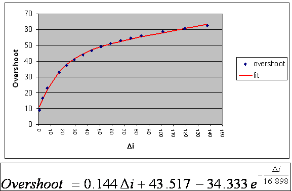
Figure 1
For example, if the right dipole is set for 0.3616 GeV/c the output current is about 126.0 Amps (with a set current of about 123.8) and the desired field is -0.13268 T. To change to +10% higher, p = 0.3978 GeV/c, should require about 10% more current or 12.6 Amps more. Instead of just typing in iset = 136.4 (123.8+12.6), do the following:
· type in iset = 153.3 (29.5 Amps more than you think you need)
· wait for the magnet to stop ramping
· type in iset = 136.4 (the setting you think you want based on the previous setting)
· Observe the field reading and its rate of change. A strip chart helps
· make small (<1 Amp), slow (>3 minutes apart) adjustments to compensate as needed.
Re the overshoot: Figure 1 is based on a model of the shorted coil with inductive coupling to the not shorted coil. As we get more experience we may refine that. In general for bigger changes more overshoot is needed. For changes less than 3 Amps just make the change and then make small adjustments. Also remember when going down the “overshoot” really is an undershoot. Always go past and then come back.
A final note: This assumes that the current in the short was zero when you started.
Comments/questions? mailto:lerose@jlab.org
Urgent questions page me 584 7624 –JJL