|
|
ES&H
Manual Flammable
Gas Supplement |

|
|
|
|
|
Chapter
2 – Examples of Gas System Class
Determination |
|
|
|
|
1.0
Purpose
This appendix provides examples of Gas System Class determination using Figure 1 in Flammable Gas Supplement Chapter 1 Storage/Use of Flammable Gases and requirements of this chapter. The first step in such an analysis is to determine the inventory in terms of hydrogen content and then to follow the Figure 1 flowchart to determine the Gas System Class. In many cases, the presence of flow and/or pressure restrictions may permit the facility to be separated into constituent parts which may be assigned different Classes.
2.0
Subdivision of a
System
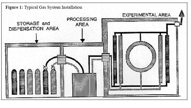
Figure
1 below is an illustration of a typical facility amenable to such separability.
The storage area is an attached building separated from a processing area which
is, in turn, separated from the experimental area. The processing area could,
for example, contain mixing apparatus or temperature regulation equipment. One
could, of course, have the processing area included within either the storage
area or the experimental hall. Each installation will differ, however both
solid walls with appropriate ventilation controls and limitations on the gas
flow to render areas separable are generally required.
In
this figure a system is shown in which two different gases (designated by
different cross-hatching) are used to supply various particle detectors. Important
details such as bubblers, check valves, orifices, shutoff valves, and gas
detectors are not shown. Note that the storage area contains several cylinders
in “off-line” storage. After passage through the particle detectors, the gases
are vented to the outdoors at the right of the figure. The precautions of this
policy are dependent upon the nature and size of the entire complex including
all flammable gases present, even if there are independent systems supplying
different particle detectors, or even different experiments in the same
building.
Figure
1. Typical Facility Amenable to
Separability
3.0
Examples of Gas System Class
Assessment
3.1
Example 1
Two 81 SCF cylinders of a 50-50 mixture (by volume) of
argon-ethane will be used in a room whose volume is 9 x 15 x 20 ft3
(2700 ft3). This room, inside a larger building, contains no obvious
fire hazards such as welding operations. The gas is to be supplied to drift
chambers.
First, to determine Q, it is recognized that only 40.5 SCF of a
given cylinder is ethane. Thus, from Flammable Gas Supplement Chapter 4 Electrical Classification Guidelines
and Chapter 5
Electrical Installation:
Q = 2 x 40.5 ft3 x 0.028(m3/ft3)
x 1.26(kg/m3) x 0.36 (H2 equivalence factor)
Q = 1.03 kg hydrogen equivalent inventory
Thus by box 1 in the flowchart, we exceed the limit for Class 0
and must go to box 2. Continuing to box
2, we find the answer to be yes but the answer to the question in box 3 is
negative. Doing the calculation prescribed in box 4 we find that 5% of 2700 ft3
is 135 ft3. Dividing 81/135
finds a maximum concentration of 60%, which exceeds the flammability upper
limit. Thus, any concentration below this limit is reachable with the available
inventory, since no inventory controls have been specified. Therefore the
answer to this question is yes and the system Class II. If only a single
cylinder was needed, the 0.5 kg hydrogen equivalence would have rendered a
Class 0 determination.
3.2
Example 2
This example is the same as that explored in example one except
that these two cylinders are used to test a drift chamber in an open
experimental hall 60 x 200 x 30 = 360,000 ft3. The nearest ignition source is a temporary brazing
operation at a distance of 40 ft (12.2 m).
Following the flowchart, the same path is found until box 4 is reached. Five
percent of this much larger room volume is 18,000 ft3. Thus the
maximum concentration in this volume would be 1.5%, so that this question is
answered negatively. At box 6, we determine that objects or operations
presenting an ignition hazard (the brazing operation) are more distant than the
2.0 m required by the formula based on the hydrogen equivalent quantity. Thus
the Gas System is Class I.
3.3
Example 3
A large system having
an inventory of 15 cylinders such as used in the first two examples is stored
in a separate “gas room” and is connected to a drift chamber system in the same
experimental hall as in example 2. The same brazing operation is continuing. There
is no processing area, only a storage area and the experimental hall. The inventory of the storage area is 15 x 0.5
kg/cylinder = 7.5 kg hydrogen equivalent. For the storage area a “yes” is
encountered at box 2 while a “no” is encountered at box 3. The volume of the
storage room is only 6 x 10 x 8 = 480 ft3 (13 m3),
however the gas inventory corresponds to a volume of 608 ft3. Thus,
without considering ventilation, the storage area will be Class II after the
query of box 4. Continuing on to the
experimental hall the interconnection is considered. If appropriate flow
restrictions exist, one may only have to consider Q to be the volume of
detectors plus piping in the hall. Thus it may be appropriate to declare the
experimental hall to be Class I, if the condition on the distance from obvious
ignition sources is met at box 6. If the
detector volumes are large, then box 4 may indicate Class II.
4.0
Revision Summary
Periodic Review –
05/06/16 – No
changes per TPOC
Revision 1.0 – 06/05/11 – New content
![]()
![]()
![]()
![]()
|
TECHNICAL POINT-OF-CONTACT |
||||