|
|
TITLE: |
||
|
|
|||
|
DOCUMENT ID: |
6200
Appendix T3 General
Electrical Safety Guidelines |
||
|
|
|||
1.0
Purpose
This appendix provides
an overview of general electrical safe work practices to be used by everyone at
Jefferson Lab. It is recognized that increased awareness of these practices
helps maintain an electrically safe work environment.
2.0
Scope
This appendix describes the electrical safe work practices used during daily operations at Jefferson Lab. This guidance does not take the place of the need for work planning, control, and authorization. This appendix is written in coordination to ES&H Manual Chapter 6200 Jefferson Lab Electrical Safety Program.
3.0
Responsibilities
NOTE: Management authority may be delegated
to a task qualified Jefferson Lab employee at the discretion of the responsible
manager.
3.1 Everyone at Jefferson Lab
· Perform work using electrical safe work practices.
· Report electrical safety hazards to your Supervisor/Subcontracting Officer’s Technical Representative /Sponsor.
· Submit a Facilities Management Work Request if new, repair, or maintenance electrical work is needed.
· Report all cases of electric shock to Jefferson Lab Occupational Medicine Department (x7539).
3.2 Qualified Electrical Worker
· Provide electrical repair or installations upon request and supervisor approval.
· Build, repair, and test power cords in accordance with Section 4.1 Power Cords.
3.3 Supervisor/Subcontracting Officer’s Technical Representative (SOTR)/Sponsor
· Ensure compliance with safe electrical work practices.
· Report electrical safety hazards to the appropriate authority.
4.0
Electrical Safe Work Practices
Power cords connect devices to power sources. They include extension cords, power strips, uninterruptible power supplies (UPS), and small appliances. Everyone at Jefferson Lab performs the following activities:
· Check cords for external defects prior to use.
· Discard those that are damaged. Permanently disable the power source, by removing the cord end(s), prior to disposal.
· Turn device(s) “off” before connecting or disconnecting power source.
· Keep cords out of the line of traffic. If unavoidable, use cord covers to prevent trip hazards and physical damage.
· Avoid “daisy-chaining” power strips, one into another.
· Extension cords can be “daisy-chained” as long as the cord wire gauge is sized adequately for the load to be served.
· Ensure that cords have adequate air circulation when in use.
· Fully insert all prongs into an outlet.
· Grasp or pull the plug, not the cord, to remove it from an outlet.
4.1.1 Build
Only Jefferson Lab qualified electrical workers are authorized to field-assemble power cords for specific use(s).
4.1.2 Repair
Only Jefferson Lab qualified electrical workers are authorized to repair power cords. The following criteria are used:
· Determine whether repair is feasible/cost-effective. If not, properly dispose of the item.
· Cords and ends are replaced with parts of equal or greater quality.
·
Electrical tape (which includes liquid
electrical tape) is never used to cover or repair damage to the outer jacket
insulation; when the inner conductors are visible.
· Repairs are checked to ensure conductors are connected to their proper terminal and for electrical continuity.
|
NOTE: Nicks and
abrasions, which do not penetrate completely through the outer jacket, are
not considered a safety concern. Repair or replacement of the extension cord
would not be required. |
4.1.3.1 Extension Cords
Extension cords are used to deliver power to a desired location on a temporary basis.
· Use as a temporary power supply.
· Unplug and store out of the line of traffic when not in use.
4.1.3.2 Power Strips
Power strips, including strip plugs and surge suppressors, are used to provide power to multiple electronic devices at one time. Use the following safety guidelines:
· Check the wattage rating to ensure compatibility with all devices connected to avoid overload.
· Do not plug one power strip into another.
· Power strips can be reset, one time, if no impeding failure is evident and the unit is not being overloaded.
4.2
Electronic
Equipment
The following administrative controls will be established when any
electrical/electronic equipment with a nominal system voltage of ≥ 50V
will be energized with engineered controls, such as protective covers or
interlocks, removed or disabled:
· Equipment shall not be left unattended unless positive physical controls are in place to prevent unqualified persons from entering the limited approach boundary and the limited approach boundary is clearly marked with ESH approved shock/arc flash boundary tape.
·
Equipment undergoing testing or maintenance
while energized requires an approved Energized Electrical Work Permit (EEWP)
unless all work will be performed outside the restricted approach boundary of
exposed conductors and circuits and the workers are not exposed to increased
likelihood of arc flash injury.
4.2.1 Approved electrical shock/arc flash boundaries
ES&H has approved the following boundary marker for use at Jefferson Lab as electrical safety boundaries. All shock/arc flash boundary tape will be 2.5” wide, red w/ white stripe tape with “Danger” in 2” black lettering. ES&H has purchased two versions of the barrier tape for laboratory use and are at the following locations:
· Portable cones with retractable barrier tape
- North/South LINAC
- East/West ARC
- Hall A, B, C, D
- Test Building
- Ted Building
· Disposable barrier tape
- Facilities
- North/South LINAC
- East/West ARC
- Test Building
- TED Building
Approved barrier tape will be available to qualified electrical workers from the stock room as requested for fieldwork.
Barrier Tape
![]()
Portable
Cones

4.3 Uninterruptible Power Supply (UPS)
UPS (desktop sized) is a battery backup unit that supplies power when there is a sag in the normal 120 VAC power. These units have a potential for shock, even when the power cord is disconnected from the wall outlet, due to stored energy. Use the following safety guidelines:
· Determination of Replacement – Contact the Computer Center (x7155) if assistance is needed to determine whether to replace the batteries or the unit. (If battery replacement is feasible, the work is to be done by a qualified electrical worker.)
· Purchase – through Jefferson Lab’s WebStock system.
· Disposal – Use Jefferson Lab’s Property Movement, Disposal or Transfer System:
o Step 1 – Click on “Submit disposal/excess of "administrative" property not on your inventory”
o Step 2 – Complete the “Property to be excessed” form to generate a work order for the UPS to be picked up for disposal.
4.4 Ground-Fault Circuit Interrupter (GFCI – Class A)
A GFCI is a device intended for the protection of personnel against electric shock. A Class A GFCI device de-energizes a circuit within an established period of time when current to ground exceeds approximately 4-6 milli-amps (mA). GFCIs at the lab come in two different configurations; 1) as permanently installed wall receptacles or circuit breakers, or 2) as portable listed cord sets that incorporate ground-fault circuit-interrupter protection for personnel.
A GFCI is required:
· In specific building/facility locations (other than dwelling units) as specified by the National Electrical Code (NFPA 70):
o Bathrooms
o Kitchens
o Rooftops
o Outdoors
o Sinks – where receptacles are installed within 6 feet of the outside edge of the sink
o Indoor wet locations
o Locker rooms with associated showering facilities
o Garages & service bay type locations
· For use with:
o Cord-and-plugged vending machines (installed after 1/1/2005).
o Electric drinking fountains (installed after 1/1/2008).
o Portable generators (15kW or smaller) – for all 125/250-volt single-phase 15-, 20-, and 30-ampere receptacles that are in use by personnel.
· With all 125-volt, single-phase, 15-, 20-, & 30-ampere receptacles outlets that are in use by personnel. The intent is to provide GFCI protection to a person working with powered (cord-and-plug) hand tools.
o When using an extension cord, the GFCI device must be installed before (ahead of) the extension cord in order to maximize the protection provided by the GFCI. A GFCI device does not protect against a fault in wiring supplying the GFCI device.
4.4.1 Testing GFCI
Jefferson Lab recommends that GFCI receptacles be tested in accordance with manufacturer’s recommendations; during safety warden inspections, and before using a temporary device that requires GFCI protection.
4.4.2 Types of GFCIs
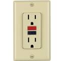
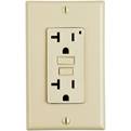
4.4.2.1 Receptacle: A GFCI receptacle is used in place of a standard outlet (see Figure 1. GFCI Receptacle). These are generally found near water sources (e.g., kitchens, bathrooms, etc.).
Figure 1. GFCI Receptacle
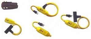
4.4.2.2 Portable: A portable GFCI is used to provide temporary power from an unprotected outlet. They are tested prior to each use (see Figure 2. Portable GFCIs).
Figure 2. Portable GFCIs
4.4.2.3 Circuit Breaker: A GFCI circuit breaker controls an entire circuit on the main panel board. In the event of a ground fault, short circuit, or overload the breaker trips and shuts off electricity to the circuit. Only those persons who have been trained by a qualified electrical worker are authorized to reset GFCI circuit breakers. Contact Facilities Management (x7400) for assistance if electricity is interrupted to your work area.
4.5 Switching (or resetting) Electrical Devices
Only those persons, who have been trained by a qualified electrical worker for the specific area, or equipment, are authorized to turn on/off or reset a circuit breaker. A minimal level of PPE, which varies between equipment types, is required during the switching operation. Electrical devices (equipment specific resets, surge suppressors/multi-outlet strips…) can be reset once, if no impeding failure is evident.
4.5.1
Response
to an Electrical Overcurrent Protection Device (ex. Circuit breaker) Fault
· Assess the situation and determine that there are no obvious failure(s)
o If unsure that a failure still exists then contact Facilities Management.
· Shed the load to the extent possible if applicable
· Clear person(s) from the immediate area(s)
· Don PPE
· Reset the overcurrent protection device
· If there is a second trip then further investigation is warranted; contact Facilities Management.
|
Exception: During an emergency, anyone at Jefferson Lab may turn on or off a circuit breaker or disconnect switch as long as doing so does not put them at risk. |
4.6 Electrical Equipment Connections
Where a tightening torque is indicated as a numeric value on equipment or in installation instructions provided by the manufacturer, a calibrated torque tool shall be used to achieve the indicated torque value, unless the equipment manufacturer has provided installation instructions for an alternative method of achieving the required torque.
4.7 Housekeeping around electrical equipment
Do not store materials on top of electrical equipment (transformers, panelboards, utilization equipment…). Keep areas clear around electrical equipment to allow access for operation and maintenance.
4.8 Capacitor Safety (storage & recycle)
Short capacitors in storage with a conductor securely fastened to the terminals and leave in place until the capacitors are returned to service. If a capacitor is scheduled for disposal, the short circuits shall remain in place.
4.9 Electrical Equipment Labeling (directory)
Panelboards, switchboards, and motor control centers are required to have an attached circuit directory (panel schedule) which clearly and legibly identifies the loads served. Spare circuits shall be identified as spares.
Equipment permanently
connected to an AC source must have the equipment disconnect location clearly
identified. Equipment which is fed from multiple power sources must clearly
identify all sources of power.
4.10 Electrical Equipment Labeling (Arc Flash and Shock Hazard)
Electrical equipment that poses a shock and/or arc flash hazard and is likely to require examination, adjustment, servicing, or maintenance while energized shall be field marked with a label containing all the following information:
1) Nominal system voltage
2) Arc flash boundary
3) At least one of the following:
a. Available incident energy and the corresponding working distance OR the arc flash PPE category in Table 130.7(C)(15)(A)(b) or Table 130.7(C)(15)(B) for the equipment
b. Minimum arc rating of clothing
c. Site-specific level of PPE
The owner of the electrical equipment shall be responsible for the documentation, installation, and maintenance of the field-marked label.
4.11 General Maintenance Requirements
Electrical equipment shall be maintained in accordance with manufacturers’ instructions or industry consensus standards to reduce the risk associated with failure. The maintenance requirements are those that are directly associated with employee safety. The equipment owner or the owner’s designated representative shall be responsible for maintenance of the electrical equipment and documentation.
4.12 Abandoned Cable Management Practices
Abandoned cable is identified as a cable that is not terminated at both ends at equipment and is not identified for future use with a tag. All accessible portion of abandoned cable shall be removed. If a cable, or portion thereof, is unable to be removed or is selected to remain for future use then the cable should be identified with a cable tag and the cable should be insulated from contact with other live electrical wiring or devices.
4.13 Wall/Blind Penetration
Jefferson Lab buildings have electrical conduit, piping, and data/communications cable within their walls and imbedded in floor slabs. It also has an extensive buried utility system on-site. Any work requiring penetration into walls, a floor, or soil, requires a Facilities Management’s Excavations and Blind Penetrations into Walls & Floors. Submit a Facilities Management Work Request to ensure compliance with this requirement.
4.14
Portable
and Vehicle-Mounted Generators
GFCI protection is required for all 125 volt, single phase, 15-, 20-, and 30- ampere receptacles on portable and vehicle-mounted generators. All other receptacle types require either GFCI protection or follow the National Electrical Code Equipment Grounding Conductor Program.
|
NOTE: The rules for grounding depend on the specific use and design of the auxiliary power generator. Therefore, if available, always refer to the manufacturers’ operation manual for further instructions. |
5.0
References
·
NFPA 70E – Standards for Electrical
Safety in the Workplace
·
NFPA 70 – National Electric
Code
·
OSHA
Regulation 29 CFR 1910 and 29 CFR 1926
·
DOE Electrical Safety
Handbook
6.0
Revision Summary
Revision 2.4 – 01/31/20 – Updated
Electrical Safe Work Practices to include Electronic Equipment and Approved
electrical shock/arc flash boundaries per CATS#NE-2019-05-04-01 and CATS#NE-2019-05-08-01
Revision 2.3 – 11/14/18 – Deleted
reference to NFPA-70E (2004 edition) per CATS# STR-2017-12-06-01; updated 4.4,
4.5; added 4.5, 4.9
Revision 2.2 – 12/16/16
– Updated Electrical Safe Work Practices for GFCI-Class A per CATS NE-2016-14-01
(T.Kujawa)
Revision 2.1 –
10/05/16 – Periodic Review; no substantive changes
Revision 2.0 – 11/03/14
– Expanded Electrical Safe Work Practices to include bullets 4.4 – 4.10;
updated reference to NFPA-70; deleted reference to IEEE and UL; per T.Kujawa
Revision 1.1 – 11/19/10 – Added general electrical safe work practices for portable and vehicle-mounted generators per T.Kujawa.
Revision 1.0 – 05/10/10 – Updated to
reflect current laboratory operations.
![]()
![]()
![]()
![]()
|
|
ISSUING
AUTHORITY |
TECHNICAL POINT-OF-CONTACT |
APPROVAL
DATE |
REVIEW DATE |
REV. |
|
|
|
ES&H Division |
01/31/20 |
01/31/23 |
2.4 |