|
|
TITLE: |
||
|
|
|||
|
DOCUMENT ID: |
6540 Appendix T4 Oxygen Deficiency Hazard (ODH) Risk Assessment |
||
|
|
|||
1.0
Purpose
An Oxygen Deficiency Hazard (ODH) Risk Assessment is performed when gas is proposed, switched, or discovered in a process or an area AND either:
· the ODH Safety Review results in an O2 percentage below 18
· the ODH Safety Reviewer requests a Risk Assessment when the resulting O2 percentage is between 18-19.5
· the ODH in question involves a complex system
· prior experience has demonstrated that a risk assessment is necessary
· as requested in accordance with ES&H Manual Chapter 3210 Work Planning, Control, and Authorization Process.
If the potential ODH is located outdoors, consult another ODH Analysis Authority or SME for the area to determine if a Risk Assessment is required. The format for the Risk Assessment shall follow the format detailed here; however, special methodologies will likely be necessary to cover the unique considerations for outdoor scenarios.
Relevant factors for all ODH Risk Assessments include, but are not limited to:
·
Volume of the area
·
Potential volume of the gas
·
Work to be performed
in the area
·
Effects produced by
reduced atmospheric oxygen
·
Likelihood of
equipment failure
·
Likelihood of human
error
·
Reliability of safety
and ventilation equipment
·
Engineering
controls currently in place and required to maintain ODH classification
·
Required administrative
controls
·
Existing ODH sources or installations
·
Ease of egress
·
Passive vent areas
·
Final ODH Classification based on analysis
2.0
Scope
This appendix provides instructions on how to complete an
ODH Risk Assessment so an accurate
determination of risk can be made, ODH Classifications can be identified and
appropriate mitigation can be implemented.
3.0
Responsibilities
NOTE:
Management authority may be delegated to a
task qualified Jefferson Lab employee at the discretion of the responsible
manager.
· Ensure an ODH Safety Review/Risk Assessment has been performed and is current for any ODH area where individuals under your authority are assigned. IT IS IMPORTANT TO CONSIDER AND MITIGATE AN ODH EARLY IN THE DESIGN/FABRICATION PROCESS.
· Review ODH Risk Assessment(s) and associated documentation every 3 years if ODH is present or when conditions change.
3.2
ODH
Analysis Authority
·
Conduct and/or review ODH Risk
Assessments when required or requested in accordance with this Appendix.
·
Upon request, perform a review of an
ODH Risk Assessment and associated documentation every 3 years if an ODH is
present.
·
Qualifications include:
o Demonstrated
ability to analyze and mitigate oxygen deficiency hazards within laboratory
user systems.
o Maintain
appropriate training SAF103 Oxygen Deficiency Hazard
o Technical
proficiencies and knowledge of:
§ ODH
evaluations, calculations, design/implementation of control measures
§ Common
compressed and liquefied gases, mixed gas properties
§ ODH
propagation calculations
§ Pressurized
gas mechanical systems with their associated failure modes analysis
o One
of the following:
§ Completion
of an engineering or physics degree, requiring four or more years of full time
study, plus a minimum of five years of experience relating to the technical
requirements listed above.
§ Professional
Engineering registration, recognized by the local jurisdiction, plus experience
in systems relating to ODH classification, mitigation, evaluation, and their
properties.
·
Submit a request for an ODH
Risk Assessment as appropriate.
·
Review the ODH Risk Assessment conclusions (Class 0,
1 or 2 designation and identification of mitigation measures) and approve risk
assessment if acceptable.
·
Distribute/File final approved ODH
Risk Assessment to affected area, Document Owner and ES&H Document Control.
·
Requests/Informs Engineering
Division Safety Systems Group of ODH system requirements.
·
Verify that ODH equipment safeguards, inventory
requirements, posting, and labeling are in-place prior to introduction of the
ODH.
·
Coordinate with DSOs to ensure ODH Risk
Assessments are reviewed every 3 years or when conditions change.
3.4
Engineering
Division
· Safety Systems Group and Cryogenic Operations: Install, maintain and calibrate area oxygen monitoring systems associated with accelerator enclosures (e.g. CEBAF, LERF, UITF) under their purview.
· Engineering Division Manager or the Cryogenic Department Head: Approve ODH Risk Assessments.
3.5
Physics
and Accelerator Divisions
·
Install, maintain and calibrate area oxygen
monitoring systems under their purview.
3.6
Facilities
Management and Logistics
· Provide room measurements upon request.
· Provide ventilation capacities upon request.
· Provide and maintain building ventilation systems.
· Install, maintain and calibrate area oxygen monitoring systems under their purview.
4.0
Expectations
An ODH Analysis
Authority may delegate the authorship of an ODH Risk Assessment to an
individual who does not meet the qualifications of an ODH Analysis Authority.
In all cases, the ODH Analysis Authority maintains responsibility for that ODH
Risk Assessment and must approve the work product as the Primary ODH Analysis
Authority.
An ODH Risk Assessment is a quantitative assessment of the increased risk of fatality from exposure to reduced atmospheric oxygen and shall be conducted for all operations which are physically capable of exposing individuals to an atmosphere below 18 % O2, or as requested by the ODH Safety Reviewer. This assessment shall assign an ODH Classification (See Table 1) to each area with potential risk as well as specify any precautionary requirements or mitigation measures. The classification of an area can change depending on the operations being performed. If conditions and/or activities change in ways that significantly increase the risk, the associated quantitative assessment must be accordingly revised, reviewed and approved.
|
Table 1. ODH Classification |
||
|
ODH Class |
# of worker-hours* during which a fatality is expected |
Φ: the ODH fatality rate (per hour) |
|
0 |
Greater than 10 million |
<10-7 |
|
1 |
from 100,000 hours to 10 million |
≥10-7 but < 10-5 |
|
2 |
from 1,000 to 100,000 |
≥10-5 but < 10-3 |
|
3 |
from 10 to 1,000 |
≥10-3 but < 10-1 |
|
4 |
less than 10 |
≥10-1 |
|
*2000 worker-hours equals one year. |
||
4.1
ODH
Risk Assessment Format
Each ODH Risk Assessment
shall follow the outlined format below including the expectations listed in the
bullets. The ODH Analysis Authority is encouraged to use previous ODH Risk
Assessments for informational purposes;
however, the format below must be used in the new ODH Risk Assessment. Examples
of approved ODH Risk Assessments can be found in the ODH Risk
Assessments and Safety Reviews folder on the ES&H Work Control
Documents pages.
4.1.1
Cover Sheet
·
Date
·
Division of ODH Analysis Authority
·
Location of ODH
·
Primary ODH Analysis Authority
·
Approvals
o At a minimum, all ODH
Risk Assessments must be approved by all of the following:
§ the Primary ODH
Analysis Authority
§ another ODH Analysis
Authority
§ the Engineering Division
Manager or the Cryogenic Department Head.
o
The ODH Risk Assessment shall be submitted to the ODH Safety Reviewer
for verification and approval.
4.1.2
Introduction
·
General information on location, equipment and ODH sources
·
Include an expected date when the ODH source will be introduced
4.1.3
Description of Work
Space
·
Details of area including volume, doorways, penetrations, venting,
etc.
·
Include figures with elevation views as appropriate
·
Describe ventilation systems and capacities
4.1.4
ODH Sources
·
Identify all potential ODH sources (helium, nitrogen, or others)
·
Include total inventory and continuous flow rates as appropriate
4.1.5
Identification of ODH
Scenarios
·
Include all possible cases for ODH determination (instantaneous
venting of entire ODH source, continuous flow into work space, etc.)
·
Consider gas mixing and stratification in defining cases
·
Clearly identify whether ventilation is included in each case
4.1.6
Risk Assessment Methodology
·
Follow the guidelines presented in Section 4.2 Estimation of ODH
Fatality Rate. Using these guidelines, the ODH Analysis Authority shall
determine the expected rate of an event occurring (Pi per hour), the expected oxygen concentration (%O2)
and the associated fatality factor (Fi) for each event. These
values are used to determine
the ODH
fatality rate (f per hour) for each identified ODH scenario.
·
The ODH Analysis
Authority may use an alternative approach provided that approach is an accepted
by another ODH Analysis Authority, the Engineering Division Manager, or
Cryogenic Department Head.
4.1.7
ODH Classification
·
Use Table 1 ODH Classification and the calculated ODH fatality
rate (f per hour) to clearly
identify Class 0, 1, or 2 for each identified ODH scenario. Class 3 and 4 are
included in the table; however, they are considered unacceptable as an ODH Risk
Assessment result. Further mitigations to lower the classification would be
necessary before the risks are considered acceptable.
4.1.8
Engineering and
Administrative Controls
·
Identify the engineering controls necessary to provide a safe
working environment and to retain ODH Classification (lintels, ventilation,
penetration sealing, etc.)
·
Identify administrative controls such as ODH monitoring, alarms
and signage
After final approval, the ODH Safety Reviewer shall distribute/file the Risk Assessment and associated documentation to the affected area, Document Owner and ES&H Document Control. The ODH Safety Reviewer shall verify ODH equipment safeguards, inventory requirements, posting, and labeling, are in-place prior to introduction of the ODH.
The ODH Risk Assessment shall
be reviewed by an ODH Analysis Authority (typically the original author if
available) every 3 years provided the ODH is present.
4.2
Estimation of ODH Fatality
Rate
The goal of ODH risk
assessment is to estimate the increase in the rate at which fatalities will
occur as a result of exposure to reduced-oxygen atmospheres.
Since the level of risk is tied to the nature of the operation,
the excess fatality rate shall be determined on an operation-by-operation
basis. For a given operation several events may cause an oxygen
deficiency. Each event has an expected rate of occurrence and each
occurrence has an expected probability of causing a fatality. The ODH fatality
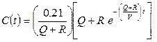
rate is defined as:

where:
f = the ODH fatality rate (per hour)
Pi = the expected rate of the ith
type of event, (per hour)
Fi = the fatality factor for the ith
type event.
The summation shall
be taken over all types of events which may cause oxygen deficiency
and result in fatality. This summation must be made for each identified ODH scenario.
Methods for determining the expected rate of an event occurring (Pi
per hour) and the fatality factor (Fi) for an event are
discussed below:
4.3
Estimation of event rates, Pi
When possible, the value of Pi
shall be determined by operating experience at Jefferson Lab; otherwise,
data from similar systems elsewhere or other relevant values shall be used. Estimates
of “spontaneous” equipment failure rates are given in Tables
2 and 3. Human error rate estimates are presented in Tables 4 and 5. Information is
presented either as a time rate (x/hr) or per demand rate (x/D).
|
System |
Failure
Mode |
Failure
Rate |
|
Compressor (Two-stage Mycom) |
Leak Component
rupture |
5 x 10⁻⁶/hr 3 x 10⁻⁷/hr |
|
Dewar |
Loss of
vacuum |
1 x 10⁻⁶/hr |
|
Electrical
Power Failure (unplanned) |
Time Rate Demand Rate Time Off |
1 x 10⁻⁴/hr 3 x 10⁻⁴/D 1 hr |
|
Fluid Line (Cryogenic) |
Leak Rupture |
5 x 10⁻⁷/hr 2 x 10⁻⁸/hr |
|
Cryogenic
Magnet (Powered,
unmanned) |
Rupture |
2 x 10⁻⁷/hr |
|
Cryogenic
Magnet (Not
powered, manned) |
Rupture |
2 x 10⁻⁸/hr |
|
Header
Piping Assembly |
Rupture |
1 x 10⁻⁸/hr |
|
U-Tube
Change (Cryogen
Release) |
Small Event Large Event |
3 x 10⁻²/D 1 x 10⁻³/D |
|
*Median
estimates excerpted from FESHM-4240 Technical Appendix, Rev 11/2016 |
||
|
Table 3: NRC and Industry Equipment Failure Rate
Estimates ** |
|
|||
|
Equipment |
Failure Mode |
Median Failure Rate |
|
|
|
Batteries Power
supplies |
No output |
3 x 10⁻⁶/hr |
|
|
|
Circuit
breakers |
Failure to
operate Premature
transfer |
1 x 10⁻³/D 1 x 10⁻⁶/hr |
|
|
|
Diesel
(complete plant) (emergency
loads) Diesel
(engine only) |
Failure to
start Failure to
run Failure to
run |
3 x 10⁻²/D 3 x 10⁻³/hr 3 x 10⁻⁴/hr |
|
|
|
Electric
Motors |
Failure to
start Failure to
run Failure to
run-extreme environment |
3 x 10⁻⁴/D 1 x 10⁻⁵/hr 1 x 10⁻³/hr |
|
|
|
Fans (fans,
motor & starter) |
Failure to
run Failure to
stat on demand |
9 x 10⁻⁶/hr *** |
|
|
|
Fuses |
Premature,
open Failure to
open |
1 x 10⁻⁶/hr 1 x 10⁻⁵/D |
|
|
|
Flanges
with Reinforced & Preformed Gaskets |
Leak, 10
mm2 opening Rupture |
4 x 10⁻⁷/hr 1 x 10⁻⁹/hr |
|
|
|
Flanges
with Packing or Soft Gaskets |
Leak, 10
mm2 opening Packing blowout Rupture |
4 x 10⁻⁷/hr 3 x 10⁻⁸/hr 1 x 10⁻⁹/hr |
|
|
|
Instrumentation (amplification,
annunciators, transducers, calibration, combination) |
Failure to
operate Shifts |
1 x 10⁻⁶/hr 3 x 10⁻⁵/hr |
|
|
|
Motorized
Louver |
Failure in
continuous operation Failure to
open on demand |
3 x 10⁻⁷/hr *** |
|
|
|
Piping |
Small
leak, 10 mm2 Pipes
>2”, large leak, 1000 mm2 Rupture |
1 x 10⁻⁹/meter-hr 1 x 10⁻¹⁰/meter-hr 1 x 10-11/meter-hr |
|
|
|
Pipes Welds D = diameter t = wall thickness |
Small
leak, 10 mm2 Pipes
>2”, large leak, 1000 mm2 Rupture |
2 x 10-11*(D/t)/hr 2 x 10-12*(D/t)/hr 6 x 10-13*(D/t)/hr |
|
|
|
Pumps |
Failure to
start Failure to
run-normal Failure to
run-extreme environment |
1 x 10⁻³/D 3 x 10⁻⁵/hr 1 x 10⁻³/hr |
|
|
|
Relays |
Failure to
energize Failure-no
contact to close Short
Across NO/NC contact Open NC
contact |
1 x 10⁻⁴/D 3 x 10⁻⁷/hr 1 x 10⁻⁸/hr 1 x 10⁻⁷/hr |
|
|
|
Solid
State Devices: Hi Power
Application |
Fails to
function Shorts |
3 x 10⁻⁶/hr 1 x 10⁻⁶/hr |
|
|
|
Solid
State Devices: Low Power
Application |
Fails to
function Shorts |
1 x 10⁻⁶/hr 1 x 10⁻⁷/hr |
|
|
|
Switches |
Limit :
Failure to operate Torque:
Failure to operate Pressure:
Failure to operate Manual:
Failure to transfer Contacts
short |
3 x 10⁻⁴/D 1 x 10⁻⁴/D 1 x 10⁻⁴/D 1 x 10⁻⁵/D 1 x 10⁻⁸/hr |
|
|
|
Transformers |
Open CKT Short |
1 x 10⁻⁶/hr 1 x 10⁻⁶/hr |
|
|
|
Valves,
Motor operated |
Failure to
operate (plug) Failure to
remain open External
leak Rupture |
1 x 10⁻³/D 1 x 10⁻⁴/D 1 x 10⁻⁸/hr 5 x 10⁻¹⁰/hr |
|
|
|
Valves,
Solenoid operated |
Failure to
operate |
1 x 10⁻³/D |
|
|
|
Valves,
Air operated |
Failure to
operate (plug) Failure to
remain open External
leak Rupture |
3 x 10⁻⁴/D 1 x 10⁻⁴/D 1 x 10⁻⁸/hr 5 x 10⁻¹⁰/hr |
|
|
|
Valves,
Check |
Failure to
open Reverse
Leak External
Leak Rupture |
1 x 10⁻⁴/D 3 x 10⁻⁷/hr 1 x 10⁻⁸/hr 5 x 10⁻¹⁰/hr |
|
|
|
Valves:
Orifice, Flow Meters (test) |
Rupture |
1 x 10⁻⁸/hr |
|
|
|
Valves,
Manual |
Failure to
remain open (plug) External
leak Rupture |
1 x 10⁻⁴/D 1 x 10⁻⁸/hr 5 x 10⁻¹⁰/hr |
|
|
|
Valves,
Relief |
Failure to
open per demand Premature
open per hour |
1 x 10⁻⁵/D 1 x 10⁻⁵/D |
|
|
|
Vessels,
Pressure |
Small
leak, 10 mm2 Disruptive
failure |
8 x 10⁻⁸/hr 5 x 10⁻⁹/hr |
|
|
|
** Estimates excerpted from FESHM-4240, Technical
Appendix, Rev 11/2016 *** If needed, reference FESHM-4240, Technical
Appendix (6.4) |
|
|||
|
Estimate error rate per demand |
Activity |
|||
|
10-3 |
Selection of a switch (or pair of switches)
dissimilar in shape or location to the desired switch, assuming no decision
error. For example, operator actuates
large handled switch rather than small switch. |
|||
|
3 x 10⁻³ |
General
human error of commission, e.g., misreading label and therefore selecting
wrong switch. |
|||
|
10-2 |
General
human error of omission where there is no display in the control room of the
status of the item omitted, e.g., failure to return manually operated test
valve to proper configuration after maintenance. |
|||
|
3 x 10⁻³ |
Errors of
omission, where the items being omitted are embedded in a procedure rather
than at the end of a procedure as above. |
|||
|
1/x |
Given that
an operator is reaching for an incorrect switch (or pair of switches), he/s he selects a particular similar appearing switch, where x =
the number of incorrect switches adjacent to the desired switch. The 1/x applies up to 5 or 6
items. After that point the error rate
would be lower because the operator would take more time to search. With up to 5 or 6 items he/she doesn’t
expect to be wrong and, therefore, is more likely to do less deliberate
searching. |
|||
|
10-1 |
Monitor or
inspector fails to recognize initial error by operator. Note: With continuing feedback of the error
on the annunciator panel, this high error rate would not apply. |
|||
|
10-1 |
Personnel
on different work shifts fail to check condition of hardware unless required
by check or written directive. |
|||
|
5 x 10⁻¹ |
Monitor
fails to detect undesired position of valves, etc., during general
walk-around inspections, assuming no check list is used. |
|||
|
0.2-0.3 |
General
error rate given very high stress levels where dangerous activities are
occurring rapidly. |
|||
|
2(n-1)x |
Given
severe time stress, as in trying to compensate for an error made in an
emergency situation, the initial rate, x, for an activity
doubles for each attempt, n, after a previous incorrect
attempt, until the limiting condition of an error rate of 1.0 is reached or
until time runs out. This limiting condition corresponds to an individual’s
becoming completely disorganized or ineffective. |
|||
|
Maximum Estimated Error
Rate per Demand |
Response
Time (sec) |
||||
|
Skill-based
Task |
Rule-based
Task |
Knowledge-based
Task |
|||
|
10-4 |
37 |
600 |
18,000 |
||
|
10-3 |
26 |
300 |
10,000 |
||
|
10-2 |
16 |
130 |
4,900 |
||
|
10-1 |
8.7 |
42 |
1,800 |
||
|
5 x 10⁻¹ |
4.0 |
10 |
550 |
||
|
1)
Skill-based Task – An individual
initiates a single-step learned response upon receipt of an unambiguous
sensor cue. (Example: A lone worker initiates escape
upon hearing an oxygen deficiency
alarm.) 2)
Rule-based Task – An
individual or small group of individuals diagnoses and initiates corrective
actions for a simple problem given limited or ambiguous input. (Example:
Several workers decide whether or not to escape given that one of them passes
out but no oxygen deficiency
alarms sound.) 3)
Knowledge-based Task – A group of
individuals diagnoses and initiates corrective
actions for a novel and/or complex problem. |
|||||
4.4
Estimation of O2
Concentration
The
ODH Analysis Authority shall calculate the %O2 for each identified
ODH Scenario considering mixing and stratification. Flow rates and oxygen
concentration over time shall be calculated as appropriate. For valuable
methodologies used in calculating %O2, consult previous ODH Risk
Assessments and/or the Fermilab guidance in FESHM 4240TA: Oxygen Deficiency Hazards (ODH) Nov. 2016
provided below. For information on gas discharge rates through relief devices
or punctures/leaks, see Reference 4, Jia, L.X. and
Wang, L. 2002 Equations for Gas Releasing
Process from Pressurized Vessels in ODH Evaluation.
(excerpted from FESHM 4240TA: Oxygen Deficiency Hazards (ODH) Nov. 2016)
The
oxygen concentration in a confined volume during and after a release of an
inert gas may be approximated with the following equations. Five different cases
are presented:
Case A: During release, with perfect mixing - Ventilation fan(s) blowing
into the confined volume
Case B: During release, with perfect mixing - Ventilation fan(s) drawing
from the confined volume with the ventilation rate greater than the spill rate
Case C: During release, with perfect mixing - Ventilation fan(s) drawing
from the confined volume with the ventilation rate less than or equal to the
spill rate
Case D: After release, with perfect mixing
Case
E: Stratification of inerting
gases
The equation and its solution are
given which are based on an oxygen mass balance for the confined volume. The
following definitions and assumptions are common for each case:
Definition
of terms:
C = oxygen concentration
Cr = oxygen concentration
during the release
Ce = oxygen
concentration after the release has ended
Q = ventilation rate of fan(s),
(cfm or m3/s)
R = spill rate into confined
volume, (scfm or m3/s)
t = time, (minutes or seconds)
beginning of release is at t=0
te = time when release has ended,
(minutes or seconds)
V = confined volume, (ft3
or m3)
Assumptions:
·
For Cases A through D, complete and instantaneous
mixing takes place in the confined volume. This is only a good assumption where
gases have similar densities and/or mixing is "vigorous."
·
Q, R, and V remain constant.
·
Pressure in the confined volume remains constant and
very near atmospheric pressure through the use of louvers or natural leakage.
·
Gas entering from outside the confined volume is air
with an oxygen concentration of 0.21 (21%).
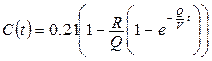
Case A: During release - Ventilation fan(s) blowing outside
air into the confined volume.
Differential equation for the oxygen mass balance
(1)
![]()
Solution with the boundary condition of C=0.21 at t=0
(2)
Case B: During release - Ventilation
fans(s) drawing contaminated atmosphere from the confined volume with the
ventilation rate greater than the spill rate (Q>R).
Differential equation for the
oxygen mass balance
(3)
![]()
Solution with the boundary
condition of C=0.21 at t=0
(4)
Case C: During release - Ventilation fans(s) drawing
contaminated atmosphere from the confined volume with the ventilation rate less
than or equal to the spill rate (Q ≤ R).
Differential equation for the oxygen mass balance
(5)
![]()
Solution with the boundary condition of C = 0.21 at t =
0
(6)
![]()
Case D: After
release - The oxygen concentration in the confined volume after the release has
ended, Ce(t), can be approximated by one
equation.
Differential equation for the oxygen mass balance
(7)
![]()
Solution with the boundary condition of C = Cr
(te) at t = te
(8)
![]()
where (t - te) is the
time duration since the release ended.
Case
E: Stratification of gases -
The effects of stratification must be considered. The oxygen concentration can
vary depending on distance from the release, elevation, gas density,
ventilation, time and other factors. In most cases simple, conservative
assumptions regarding mixing are more suitable than attempting a precise
evaluation of mixing. For large enclosures it may be reasonable to assume
complete mixing in a portion of the volume. Stratification should not be
used to reduce the risk.
4.5
Fatality Factor, Fi
The
value of Fi
is the probability
that a person will die if the ith event occurs. This value depends on the oxygen
concentration, the duration of exposure, and the difficulty of escape. For
convenience of calculation, a relationship between the value of Fi and the lowest attainable
oxygen concentration is defined (Figure 1). (The lowest concentration is used
rather than an average since the minimum value is conservative and not enough
is understood to allow the definition of an averaging period.)
Once
% O2 has been identified for each ODH Scenario, the ODH Analysis
Authority shall identify the associated Fatality Factor (Fi) using Figure 1.
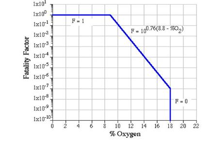
Figure 1: Fatality Factor (Fi) vs lowest attainable 02 concentration
resulting from a given event
If the
lowest oxygen concentration is greater than 18%, then the value of Fi is zero. That is, all
exposures above 18% are defined to not contribute to fatality. It is assumed
that all exposures to 18% oxygen or lower do contribute to fatality and the
value of Fi
is designed to
reflect this dependence.
If the
lowest attainable oxygen concentration is 18%, then the value of Fi is 10-7. This
value would cause f to be 10-7 per hour if the expected rate of
occurrence of the event were one per hour. At decreasing concentrations, the
value of Fi should
increase until, at some point, the probability of dying becomes unity. That
point was selected to be 8.8% oxygen, the concentration at which one minute of
consciousness is expected.
5.0
References
·
FESHM 4240: Oxygen Deficiency Hazards (ODH), Fermilab ES&H
Manual, November 2016.
·
Jefferson Lab ODHRAP [formerly ES&H Manual Chapter 6500
Appendix T3 Oxygen Deficiency Hazard (ODH) Risk Assessment].
·
Reactor Safety Study: An Assessment
of Accident Risks in US Commercial Power Plants Appendix 3&4: Failure Data,
US Nuclear Regulatory Commission; US Department of Commerce-National Technical
Information Service, PB-248 204, October 1975.
·
Jia, LX and Wang, L 2002, ‘Equations for
Gas Releasing Process from Pressurized Vessels in ODH Evaluation’, in S Breon, et al. (eds.), CP613, Advances in Cryogenic Engineering: Proceedings of the Engineering
Conference, Vol.47, 2002 American Institute of Physics, pp. 1792-8.
6.0
Revision Summary
Revision 0.0
– 10/31/17 – Initial content
![]()
![]()
![]()
![]()
|
|
ISSUING AUTHORITY |
TECHNICAL POINT-OF-CONTACT |
APPROVAL DATE |
REVIEW DATE |
REV. |
|
|
|
ES&H
Division |
11/06/17 |
11/06/20 |
0.0 |
|
This document is controlled as an on
line file. It may be printed but the
print copy is not a controlled document.
It is the user’s responsibility to ensure that the document is the same
revision as the current on line file.
This copy was printed on 11/7/2017.